Features
Function and Description
Highly Developed Low-Pressure Reducing Valve
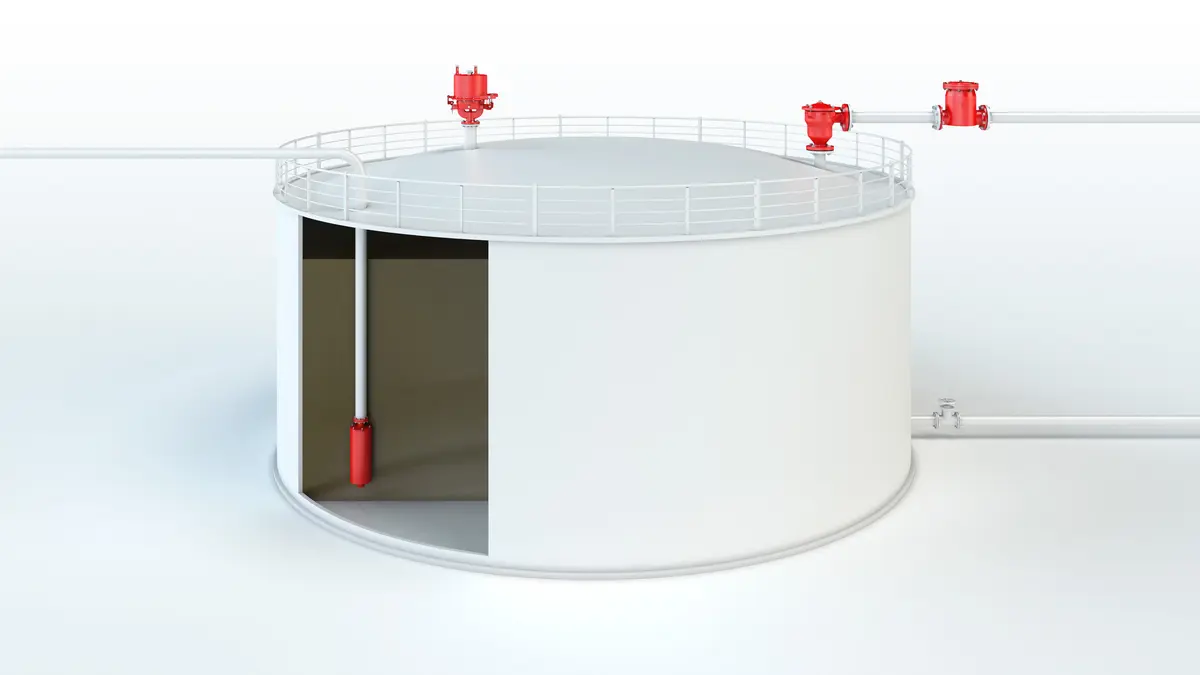
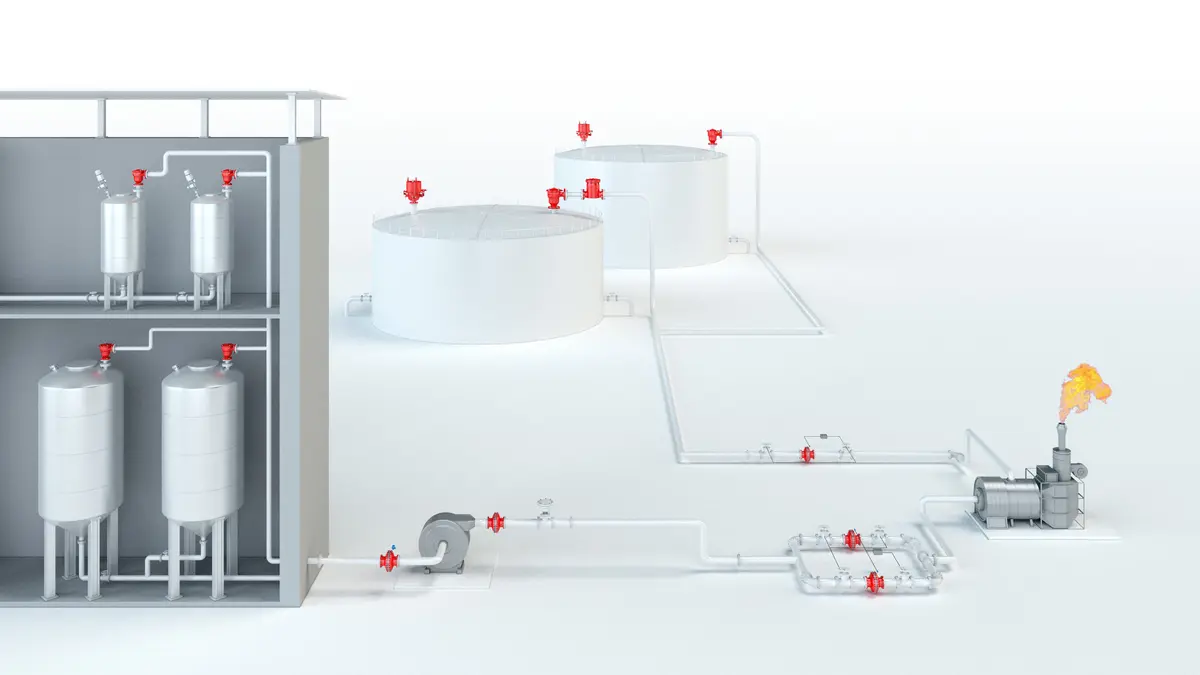
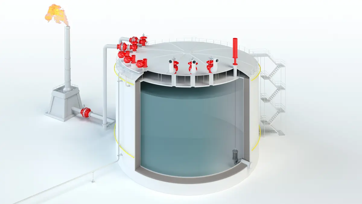
The Blanketing Valve Type ZM-R is a highly developed low pressure reducing valve Réducteur de pression A pressure reducing valve reduces a higher, fluctuating inlet pressure to a lower, constant outlet pressure. . This valve is typically used to inert or blanket tanks, vessels, or other process systems with Nitrogen or other blanketing gases by controlling the tank pressure Pression de la cuve Tank pressure is the pressure within a tank. to ist desired value. High Nitrogen or blanketing gas supply pressures up to 16 bar / 232 psi are safely reduced down to only a few mbar / inch W.C..
Membrane-Controlled and Spring-Loaded Proportional Regulator
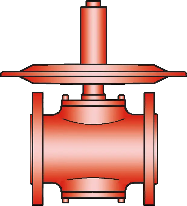
The ZM-R low pressure reducing valve is a direct acting, one stage pressure control device Appareil A device is a pipe component that influences the media flow by opening, closing, or partially shutting off the flow channel or by dividing or mixing the media flow. . It is designed as a diaphragm Membrane A diaphragm is a thin layer of material, which has a large surface area. controlled, spring Ressort A spring is a spiral of wire which returns to its original shape after it is pressed or pulled. -loaded proportional acting valve. The valve controls the tank pressure by increasing flow as the tank pressure drops. This means that the mass flow through the valve depends on the pressure differential of the set pressure Pression de réponse Set pressure is the gauge pressure at the device inlet at which the relief device is set to start opening under service conditions. to the actual tank pressure. When the actual tank pressure reaches the set pressure, the control unit closes, and there is no flow.
For Precise Pressure Control
At the control diaphragm, (which can be made from PTFE or Viton), the tank pressure (P2) is balanced with the adjustment spring and the supply pressure (P1). In a depressurized tank, the adjustment spring holds the valve pallet Clapet Valve pallet is the generic term for the assembly that rests on the valve seat. in the fully open position. As the tank pressure increases, the valve pallet moves toward the seat, and the mass flow is reduced. When the desired tank pressure is reached, the valve will close.
Precise Pressure Control up to -200 mbar
If the tank pressure decreases, the valve will open. If the system is operated in a vacuum Dépression Vacuum is the pressure in an enclosed space that is lower than the ambient pressure. mode, vacuum pressures down to -200 mbar /-80 inch W.C. (relative pressure) can be achieved.
Dimensions
To select the nominal size Diamètre nominal The nominal size is an alphanumeric designation of size for components in a piping system, used for reference purposes, comprising the letters DN followed by a dimensionless integer that is indirectly related to the physical size of the bore or outside diameter of the connections, expessed in millimeters. (DN), please use the flow capacity charts on the following pages
| DN | 15 / ½" | 25 / 1" | 50 / 2" | 15 / ½" | 25 / 1" | 50 / 2" | |
| a | 214 | 214 | – | 8.43 | 8.43 | – | |
| b | 168 | 168 | – | 6.61 | 6.61 | – | |
| c* | – | – | 214 / 360 | – | – | 8.43 / 14.17 | |
| d | DIN | 150 | 160 | 150 | 5.91 | 6.3 | 5.91 |
| ANSI | 180 | 160 | 150 | 7.09 | 6.3 | 5.91 | |
| e | 214 | 214 | 230 | 8.43 | 8.43 | 9.06 | |
| f | 87 | 87 | 103 | 3.43 | 3.43 | 4.06 |
Dimensions in mm / inches
*depends upon size of diaphragm
Dimensions
Selection of valve seat Siège de soupape The valve seat is a component on which the valve pallet rests when the valve is closed. depending on flow rate
| Size | Seat in mm / inches | Kvs | Number |
| 25 / 1'' | 2,0 / 0.08 | 0,15 | 20 |
| 4,5 / 0.18 | 0,60 | 45 | |
| 7,5 / 0.30 | 1,20 | 75 | |
| 10,0 / 0.39 | 1,70 | 100 | |
| 14,0 / 0.55 | 2,40 | 140 | |
| 50 / 2'' | 14,0 / 0.55 | 2,80 | 140 |
| 18,0 / 0.71 | 6,80 | 180 | |
| 26,0 / 1.02 | 14,50 | 260 |
*1 Kvs = 0.86 Cv; 1 Cv = 1.17 Kvs
Material selection for housing
| Design | S | H | |
| Housing | Stainless Steel | Hastelloy | |
| Valve seat | Stainless Steel | Hastelloy | |
| Valve pallet | Stainless Steel | Hastelloy | |
| Valve seat sealing | FFKM | FFKM | |
| Gasket | PTFE | PTFE | |
| Diaphragm P | PTFE | PTFE | Marking P |
| Alternative: Diaphragm V | Viton | - | Marking V |
Optional: Inner part of housing Corps A housing is a solid shell, which surrounds a content, either protecting the content from external influences, or protecting the environment from the content. electropolished. Special materials upon request
Type of connection
| FD | DIN 2501, PN 16 | DIN |
| FA | ASME B16.5 CL 150 R.F. | ASME |
| G | Thread | G or NPT |
other types upon request
Design Types and Specifications
Two different designs are available:Other special devices can be supplied on request
For in-line valves any
back pressure
Contre-pression
The back pressure is the sum of built-up back pressure and superimposed back pressure.
, which will influence the set pressure and opening characteristics, has to be taken into account.
Settings
| Supply pressure: | +16 bar | |
| +6424 inch W.C. | ||
| Set pressure for overpressure function: | +500 mbar | |
| +200 inch W.C. | ||
| Set pressure for vacuum function: | -200 mbar | |
| -80 inch W.C. |
Flow rates for P2 pressure range (Europe - metric units)
ZM-R 15 / ZM-R 25: flow rate (air, 0°C) at ∆P = P1 - P2 and valve full open
| P 1 (bar) | 0,15 | 0,25 | 0,40 | 0,65 | 1,00 | 1,50 | 2,50 | 4,00 | 6,00 | 10,00 | Sitz-Ø |
| P 2 (mbar) | [Nm³ / h] | [Nm³ / h] | [Nm³ / h] | [Nm³ / h] | [Nm³ / h] | [Nm³ / h] | [Nm³ / h] | [Nm³ / h] | [Nm³ / h] | [Nm³ / h] | [mm] |
| 10 | 6,2 12,4 17,5 24,8 | 8,1 16,2 23,0 32,5 | 10,3 20,7 29,3 41,4 | 13,2 26,5 37,6 53,1 | 16,5 33,0 46,7 66,0 | 20,6 41,2 58,4 82,4 | 28,8 57,6 81,6 115,2 | 41,1 82,2 116,5 164,5 | 57,5 115,0 163,0 230,1 | 90,3 180,7 256,0 361,4 | Ø4,5 Ø7,5 Ø10,0 Ø14,0 |
| 20 | 6,0 12,0 17,0 24,0 | 7,9 15,9 22,6 31,9 | 10,2 20,5 29,1 41,1 | 13,2 26,4 37,5 52,9 | 16,5 33,0 46,7 66,0 | 20,6 41,2 58,4 82,4 | 28,8 57,6 81,6 115,2 | 41,1 82,2 116,5 164,5 | 57,5 115,0 163,0 230,1 | 90,3 180,7 256,0 361,4 | Ø4,5 Ø7,5 Ø10,0 Ø14,0 |
| 100 | 3,8 7,7 10,9 15,4 | 6,7 13,4 18,9 26,8 | 9,4 18,9 26,8 37,9 | 12,8 25,6 36,3 51,3 | 16,4 32,8 46,5 65,6 | 20,6 41,2 58,4 82,4 | 28,8 57,6 81,6 115,2 | 41,1 82,2 116,5 164,5 | 57,5 115,0 163,0 230,1 | 90,3 180,7 256,0 361,4 | Ø4,5 Ø7,5 Ø10,0 Ø14,0 |
| 200 | - - - - | 4,0 8,0 11,4 16,1 | 8,00 16,1 22,9 32,3 | 12,1 24,2 34,3 48,4 | 16,1 32,3 45,8 64,6 | 20,6 41,2 58,4 82,4 | 28,8 57,6 81,6 115,2 | 41,1 82,2 116,5 164,5 | 57,5 115,0 163,0 230,1 | 90,3 180,7 256,0 361,4 | Ø4,5 Ø7,5 Ø10,0 Ø14,0 |
| 500 | - - - - | - - - - | - - - - | 7,8 15,6 22,1 31,2 | 14,2 28,5 40,4 57,0 | 20,1 40,3 57,1 80,7 | 28,8 57,6 81,6 115,2 | 41,1 82,2 116,5 164,5 | 57,5 115,0 163,0 230,1 | 90,3 180,7 256,0 361,4 | Ø4,5 Ø7,5 Ø10,0 Ø14,0 |
Flow rates for P2 pressure range (Europe - metric units)
ZM-R 50: flow rate (air, 0°C) at ∆P = P1 - P2 and valve full open
| P 1 (bar) | 0,15 | 0,25 | 0,40 | 0,65 | 1,00 | 1,50 | 2,50 | 4,00 | 6,00 | 10,00 | Sitz-Ø |
| P 2 (bar) | [Nm³ / h] | [Nm³ / h] | [Nm³ / h] | [Nm³ / h] | [Nm³ / h] | [Nm³ / h] | [Nm³ / h] | [Nm³ / h] | [Nm³ / h] | [Nm³ / h] | [mm] |
| 10 | 28,9 70,3 150,0 | 37,9 92,1 196,5 | 48,3 117,4 250,4 | 61,9 150,4 320,8 | 77,0 187,1 399,1 | 96,2 233,6 498,3 | 134,5 326,6 696,5 | 191,9 466,1 994,0 | 268,5 652,1 1390 | 421,6 1024 2183 | Ø14,0 Ø18,0 Ø26,0 |
| 20 | 28,0 68,1 145,3 | 37,3 90,6 193,3 | 47,9 116,5 248,4 | 61,7 150,0 319,9 | 77,0 187,1 399,0 | 96,2 233,6 498,3 | 134,5 326,6 696,5 | 191,9 466,1 994,0 | 268,5 652,1 1390 | 421,6 1024 2183 | Ø14,0 Ø18,0 Ø26,0 |
| 100 | 18,0 43,8 93,5 | 31,2 75,9 162,0 | 44,2 107,4 229,1 | 59,9 145,5 310,2 | 76,6 186,1 396,9 | 96,2 233,6 498,3 | 134,5 326,6 696,5 | 191,9 466,1 994,0 | 268,5 652,1 1390 | 421,6 1024 2183 | Ø14,0 Ø18,0 Ø26,0 |
| 200 | - - - | 18,8 45,8 97,6 | 37,7 91,6 195,3 | 56,5 137,4 293,0 | 75,4 183,2 390,6 | 96,2 233,6 498,3 | 134,5 326,6 696,5 | 191,9 466,1 994,0 | 268,5 652,1 1390 | 421,6 1024 2183 | Ø14,0 Ø18,0 Ø26,0 |
| 500 | - - - | - - - | - - - | 36,4 88,6 188,9 | 66,6 161,7 344,9 | 94,1 228,7 487,8 | 134,5 326,6 696,5 | 191,9 466,1 994,0 | 268,5 652,1 1390 | 421,6 1024 2183 | Ø14,0 Ø18,0 Ø26,0 |