TS/P, TS/E, TS/W
Hydraulic Flame Arresters deflagration proof, detonation proof and short-time burning proof
Features
Function and Description
Protection of Explosion-Prone Process Plants
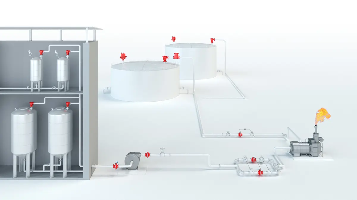
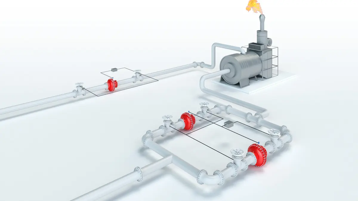
The PROTEGO® type TS/… Series of Hydraulic Flame Arresters are mainly designed to protect process plants which are connected to waste thermal combustion units. Hydraulic Flame Arresters of the TS/… series are particularly suitable to protect plants which supply heavily contaminated, sticking, polymerizing or even foaming substances into thermal combustion units. Generally, it is necessary to protect the plant against in-line deflagration, stable detonation, and endurance burning Endurance burning Stabilized burning for an unlimited time. hazards, and consider the plant‘s operating conditions.

Many Individual Certifications
The PROTEGO® TS/… Series of Hydraulic Flame Arresters guarantees flame transmission protection during short-time burning, deflagration, and stable detonation of gas/air mixtures or product vapor/air mixtures of the relevant explosion groups in all ranges of flammable concentrations with a service temperature of up to +60 °C / 140 °F and an operating pressure Pression de service Operating pressure is the pressure existing at normal operating conditions within the system being protected. up to 1.1 bar / 15 psi (absolute). Flame Arresters of type TS/… are the only Hydraulic Flame Arresters which have been tested and certified for substances of all explosion groups. EU conformity according to the currently valid ATEX directive. Approvals according to other national/international regulations on request.
Main Component - Immersion Tank
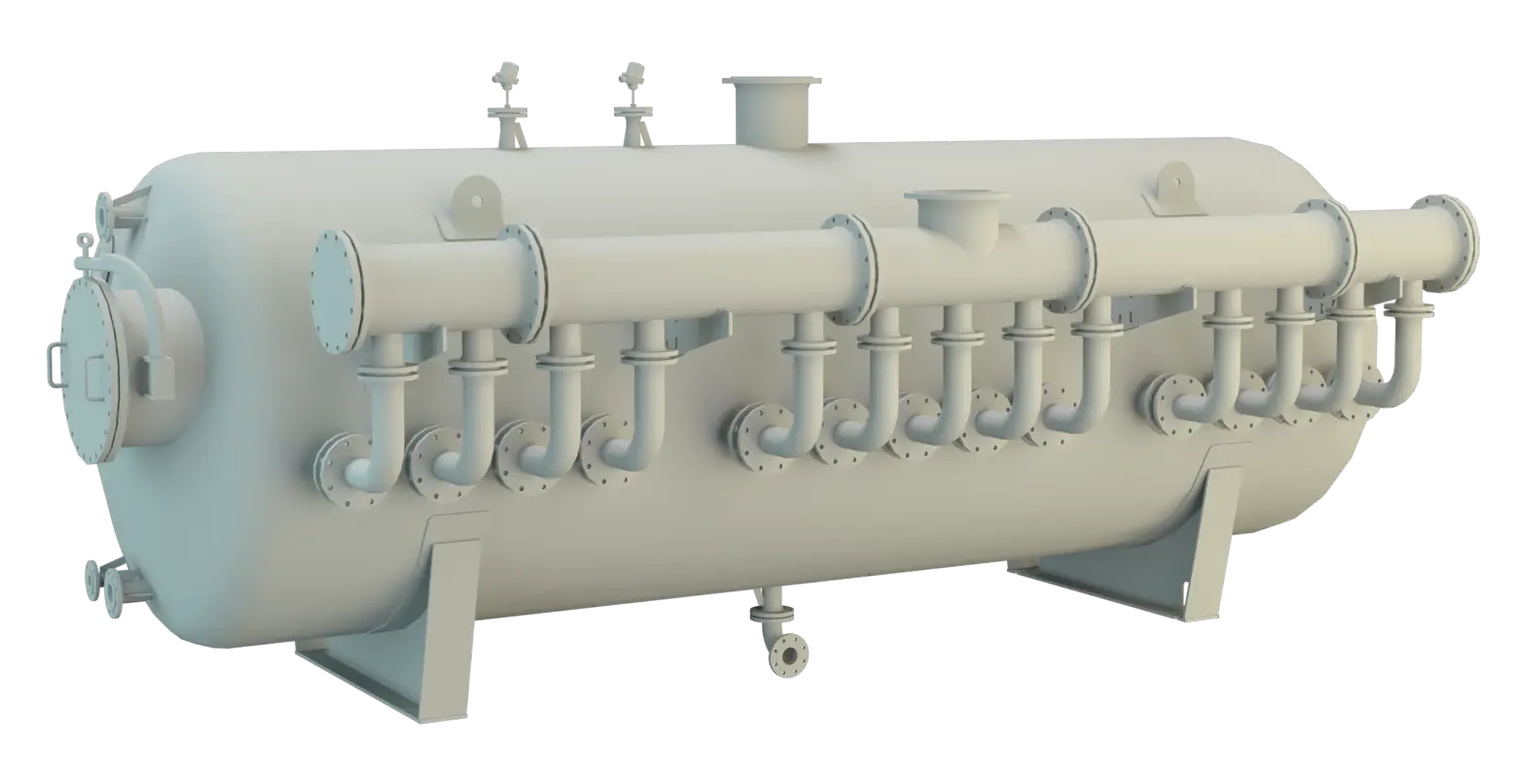
Hydraulic Flame Arrester of Series TS/… mainly consist of the immersion tank (1) with exhaust air nozzle and connection nozzles for the sparge pipes, the sparge pipes (2) with elbows and connection flanges as well as the manifolds (3) with connection flanges. To allow measurement of the immersion liquid temperature, the tank (1) has a minimum of one nozzle (5) and, for measuring the temperature of the exhaust gas, there is a minimum of one connection for each exhaust air nozzle (6) for inserting temperature sensors. Additionally, the tank has two nozzles (7, 8) for level measurement, two nozzles (9, 10) for level control, and one nozzle (11) for draining. Inspection glasses (4) are included for inspection of the immersion liquid and gas space.
Removing the Sparge Pipes Makes Cleaning Easier
The sparge pipes can be pulled out of the Hydraulic Flame Arrester to allow cleaning of the drill holes and pipes. They contain the appropriate flange connections for the supply of exhaust air and, depending on the distribution of the exhaust air flow, the number of nozzles for distribution to the sparge pipes.
Flame Backfire Is Prevented
In PROTEGO® Type TS/… Hydraulic Flame Arresters. The flammable mixtures are passed through a water seal Joint A seal prevents or limits unwanted transfer of product from one container to another. Seal is used as superordinate term for all types of sealing elements. with a defined immersion depth. The mixture flow is divided and supplied evenly to the individual sparge pipes. The sparge pipes have small drill holes, which produce defined bubble columns. In case of an ignition in the flowing gas mixture, the flame is prevented from returning into the inlet line. The following parameters have a significant effect on the flame arresting efficiency of the device Appareil A device is a pipe component that influences the media flow by opening, closing, or partially shutting off the flow channel or by dividing or mixing the media flow. in case of deflagrations, detonations, or short-time burning: • Mixture volume flow • Immersion depth from the water seal‘s surface to the upper edges of the drill holes in the sparge pipes, • Water temperature in the hydraulic flame arrester Arrête-flammes hydraulique Flame arrester designed to break the flow of an explosive mixture into discrete bubbles in a water column, thus preventing flame transmission. • Precise drill hole diameter in the sparge pipes due to size, form, and density of the bubbles.
Ensures Limited Ignition Transmission Safety
If the mixture ignites under certain operating conditions within the Hydraulic Flame Arrester and burns directly on the liquid surface, prevention of flame transmission can only be guaranteed for a limited amount of time. So, several temperature sensors are installed in the gas space, and, when reaching a specified temperature, they trigger appropriate emergency functions upstream in the connected system (shut down, inerting, etc.).
Requirements for Hydraulic Flame Arrester
A high accuracy volume flow meter must be installed as an essential technical safety element. It has to guarantee that the maximum allowable volume flow, on which the design of the Hydraulic Flame Arrester has been based, is recorded and limited so that emergency functions are triggered if the exhaust air volumes exceed the safe level. In addition, a minimum flame transmission-proof Flame transmission-proof Characteristic of a device to avoid flashback. immersion height is necessary, i.e. an adequate water level must be guaranteed by suitable measuring equipment. The pressure loss of a hydraulic flame arrester at maximum volume flow results from the inlet and outlet losses of approximately 12 to 18 mbar / 4.8 to 7.2 inch W.C. plus the immersion depth, e.g. 350 mm = 35 mbar / 13.8 In = 14.1 inch W.C., so the total is between 47 and 53 mbar / 18.9 and 21.3 inch W.C.
Instrumentation
The efficiency and function of the PROTEGO TS/… hydraulic flame arrester requires measurement and control equipment for the filling level, volume flow and temperature of the system. It is necessary to maintain the minimum operating immersion depth and measure the maximum mixture volume flow, maximum gas temperature and minimum water temperature. If the safe operational envelope is exceeded, the measurement and control equipment must quickly initiate automatic emergency functions. Measurement and control safety equipment must be explosion proof and approved for zone 0.
Measurement and control equipment is not part of standard scope of supply.
Data Necessary for Specification
Die sicherheitstechnische Auslegung der Tauchsicherung erfordert die relevanten Betriebsdaten:Gemischvolumenstrom unter der Berücksichtigung des max. möglichen Volumenstroms (m3/h)
Gemischzusammensetzung (Vol.%)
Betriebstemperatur (°C)
Temperaturmessung und -begrenzung
In order to prevent endurance burning in the arrester the off gas supply must be stopped automatically when the temperature exceeds T = 80°C / 176°F at the gas outlet. Temperature sensors monitor the mixture temperature.
If the water temperature falls below T < 10°C / 50°F (danger of freezing) or rises above the limiting temperature in the gas space, a quick action gate valve must shut automatically and stop the off gas supply.
As an option temperature sensors can be supplied.
Flange connection type
The standard flange connections are made to EN 1092-1 or DIN 2501, PN 16 (from DN 200, PN 10). Optionally, the connecting flanges can be made according to any international standard.Temperature Measurement and Limitation
The operating immersion depth should be kept constant by a controlled automatic water supply so that the level does not fall below the minimum immersion depth.Selection and Design
The static immersion depth and the resistance due to dynamic flow in the sparge pipes and the off gas supply lines create the total pressure loss. The manufacturer’s advice about technical safety is absolutely necessary in any case!
For particularly corrosive mixtures the hydraulic flame arrester may be coated. The materials of tank, installations and sparge pipes have to be selected according to the corrosive properties of the mixture.
Design Types and Specifications
The hydraulic flame arresters are designated by explosion groups, diameters and numbers of sparge pipes.They are designed in modules and type tested for the corresponding explosion groups.
The number of sparge pipes depends on the design volume flow.
Example: TS/E-1000-5 is a hydraulic flame arrester for substances of explosion group IIB3 (NFPA group C) with a diameter of 1000 mm / 40” and 5 sparge pipes.
Maximum Volume Flow
The maximum allowable operating volume flow is calculated by multiplying the number of sparge pipes by the maximum allowable operating volume flow for each sparge pipe Sparge pipe Inlet pipe into the stored substances of a hydraulic flame arrester. at its immersion depth.
In special cases it may not be necessary to measure the volume flow provided that the volume flow limitation is guaranteed by other components in the system such as a conveyor system or a choke in combination with a decompression device.