Features
Function and Description
Combined Pressure and Vacuum Relief Valve
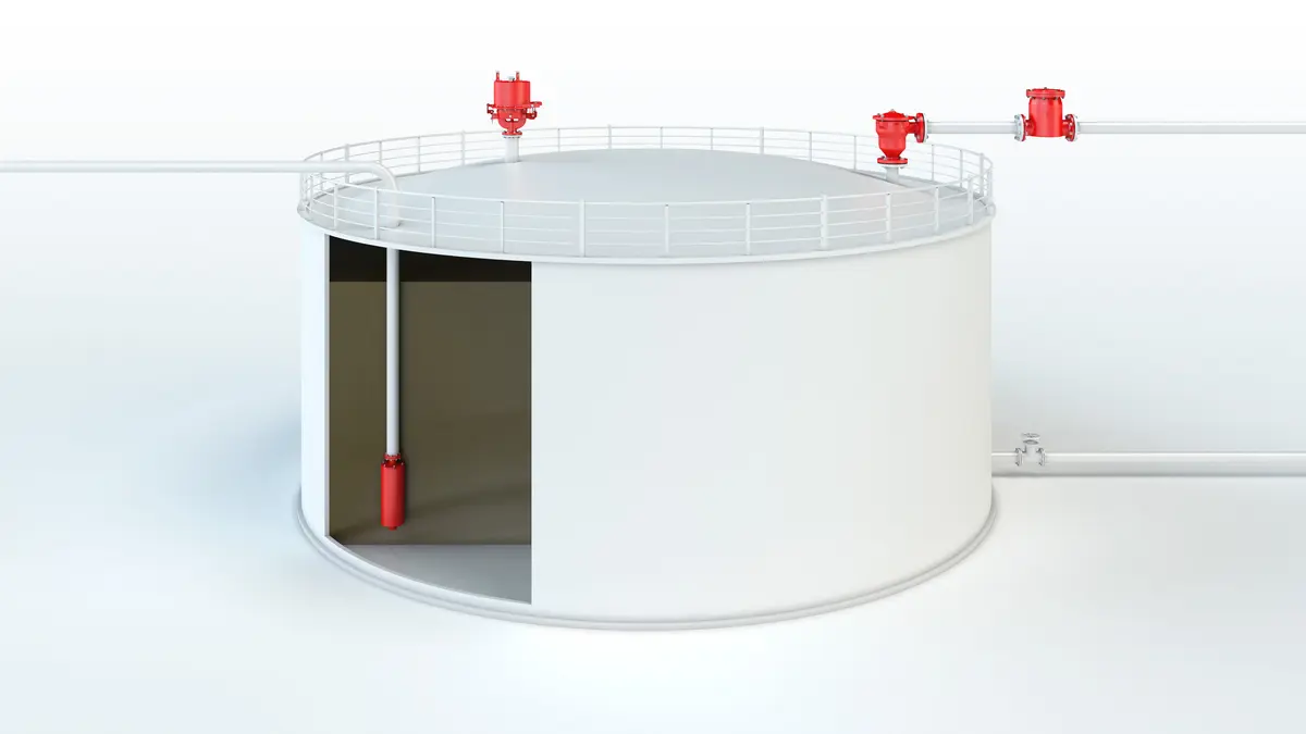
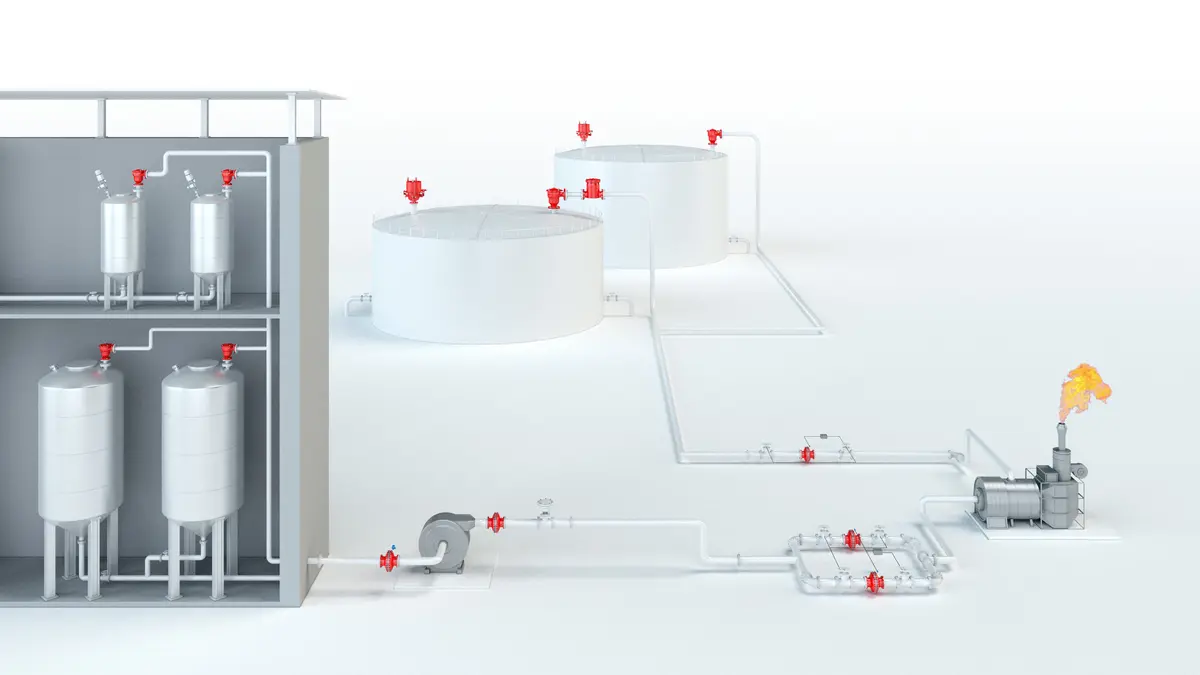
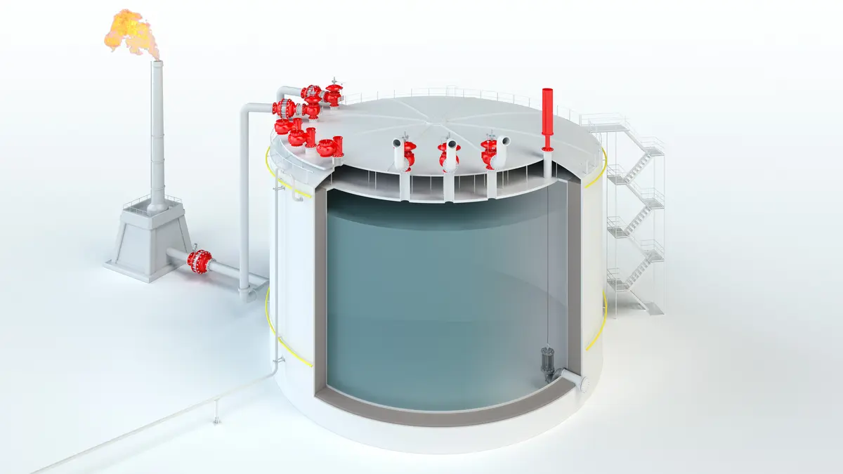
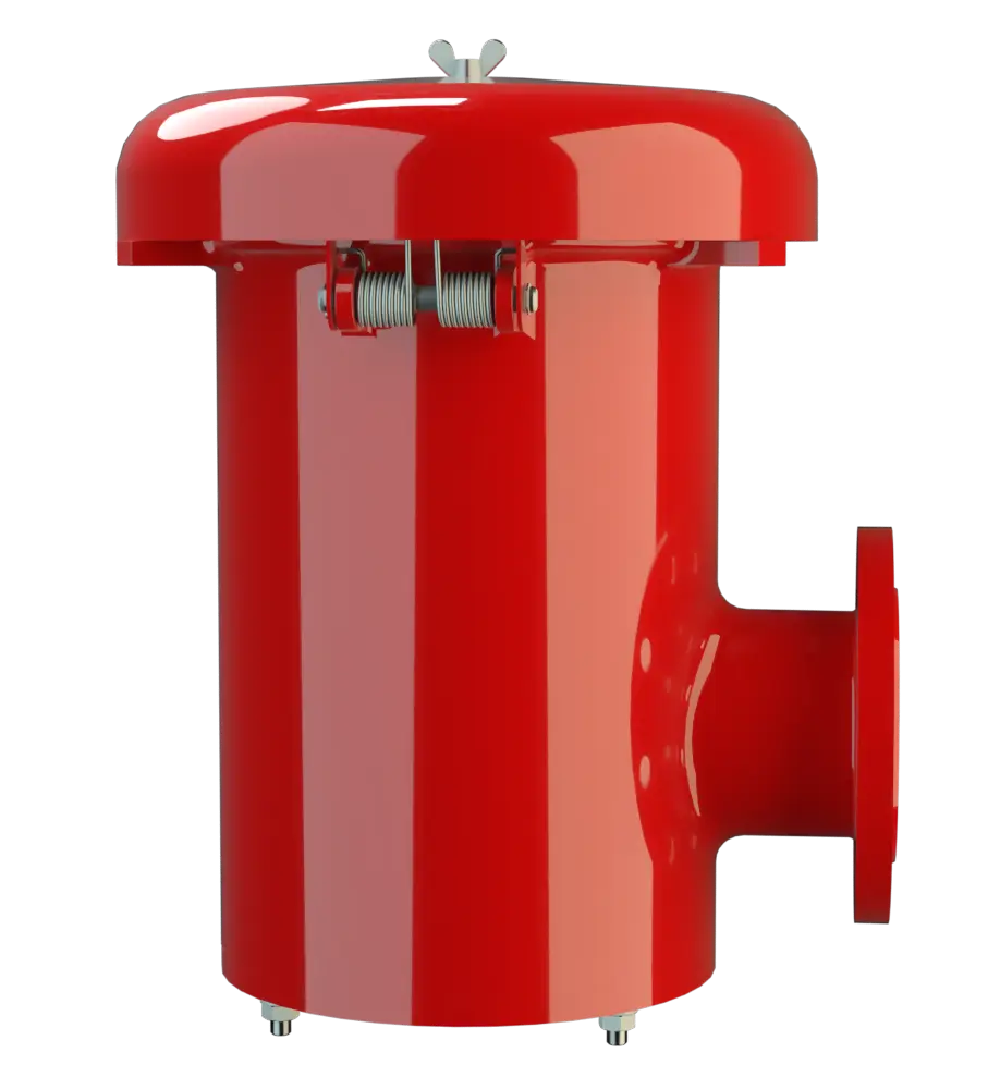
The PV/ELR Type PROTEGO® valve is a highly developed combined pressure and vacuum relief valve Soupape de surpression et dépression A pressure and vacuum relief valve is a pressure equalization valve for impermissible pressure and vacuum in a closed system. with excellent flow performance. Typically, the valve is installed in the in-breathing and out-breathing lines of tanks, vessels, and process equipment to protect against unallowable overpressure Surpression Overpressure refers to an increase in pressure in a system or vessel above the normal operating pressure. and underpressure. The valve prevents emission losses almost up to the set pressure Pression de réponse Set pressure is the gauge pressure at the device inlet at which the relief device is set to start opening under service conditions. and air intake almost up to the set vacuum Set vacuum Internal negative gauge pressure at which a vacuum valve first opens. .
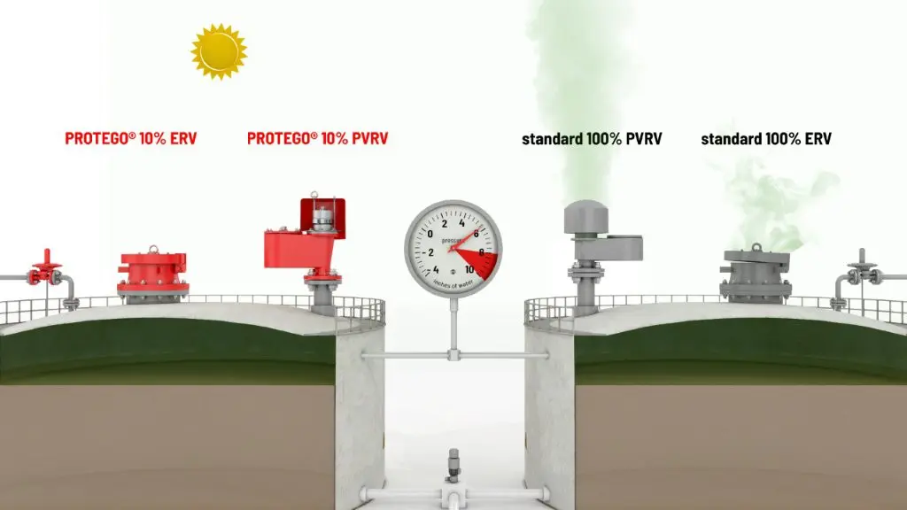
Full Lift Technology
The device Appareil A device is a pipe component that influences the media flow by opening, closing, or partially shutting off the flow channel or by dividing or mixing the media flow. will start to open as soon as the set pressure is reached and only requires 10% overpressure to full lift Course Lift is the actual travel of the valve pallet from the main valve out of the closed position. . Continuous investments in and a commitment to research and development have allowed PROTEGO® to develop a low pressure valve which has the same opening characteristic as a high pressure safety relief valve. This “Full Lift Type” technology allows the valve to be set at just 10% below the maximum allowable working pressure or vacuum Dépression Vacuum is the pressure in an enclosed space that is lower than the ambient pressure. (MAWP or MAWV) of the tank and still safely vent the required mass flow. The opening characteristic is the same for pressure and vacuum relief.
Advanced Manufacturing Technology
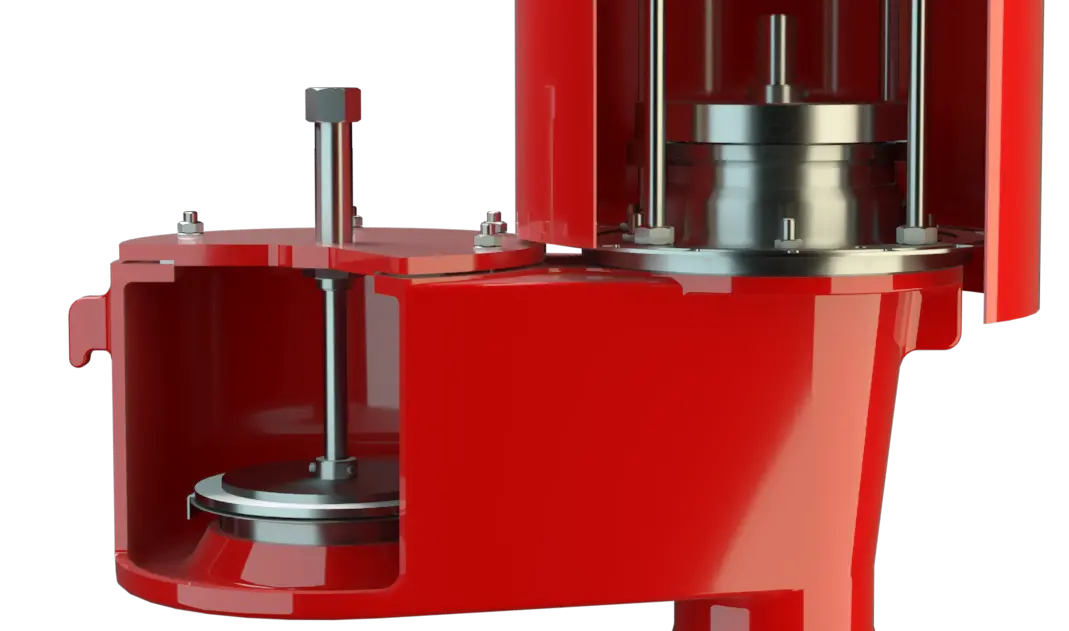
Due to the highly developed manufacturing technology, the tank pressure Pression de la cuve Tank pressure is the pressure within a tank. is maintained up to the set pressure, with a tightness that is far superior to the conventional standard. This feature is achieved by valve seats made of high quality stainless steel and with precisely lapped valve pallets (1) or with an air cushion seal Joint A seal prevents or limits unwanted transfer of product from one container to another. Seal is used as superordinate term for all types of sealing elements. (2) in conjunction with high quality FEP diaphragm Membrane A diaphragm is a thin layer of material, which has a large surface area. . The valve pallets are also available with a PTFE seal to prevent the valve pallet Clapet Valve pallet is the generic term for the assembly that rests on the valve seat. from sticking when sticky products are used, and they enable the use of corrosive substances. After the overpressure is released or the vacuum is balanced, the valve re-seats and provides a tight seal. The optimized fluid dynamic design of the valve body and valve pallet is a result of many years of research, resulting in stable operation of the valve pallet, optimized performance, and reduced product losses.
Dimensions
To select the nominal size Diamètre nominal The nominal size is an alphanumeric designation of size for components in a piping system, used for reference purposes, comprising the letters DN followed by a dimensionless integer that is indirectly related to the physical size of the bore or outside diameter of the connections, expessed in millimeters. (DN), use the flow capacity chart on the following page
| DN | 80 / 3" | 80 / 3" | 100 / 4" | 100 / 4" |
| Set pressure | ≤ +35 mbar | > +35 mbar | ≤ +35 mbar | > +35 mbar |
| Set pressure | ≤ +14 inch W.C. | > +14 inch W.C. | ≤ +14 inch W.C. | > +14 inch W.C. |
| a | 345 / 13.58 | 475 / 18.70 | 345 / 13.58 | 475 / 18.70 |
| b | 146 / 5.75 | 146 / 5.75 | 146 / 5.75 | 146 / 5.75 |
| c | 218 / 8.58 | 218 / 8.58 | 218 / 8.58 | 218 / 8.58 |
| d | 353 / 13.90 | 353 / 13.90 | 353 / 13.90 | 353 / 13.90 |
Dimensions in mm / inches
Dimensions for pressure/ vacuum relief valve Soupape de dépression A vacuum relief valve is used to ventilate a part of the system and protects it from impermissible underpressure. with heating jacket upon request
Material selection for housing
| Design | B | C |
| Housing | Steel | Stainless Steel |
| Heating jacket (PV / ELR-H-...) | Steel | Stainless Steel |
| Valve seat | Stainless Steel | Stainless Steel |
| Weather hood | Steel | Stainless Steel |
| Protective mesh screen | Stainless Steel | Stainless Steel |
Special materials upon request
Material selection for pressure valve pallet
| Design | A | B | C | D |
| Pressure range [mbar] [inch W.C.] | +2.0 up to +3.5 +0.8 up to +1.4 | >+3.5 up to +14 >+1.4 up to +5.6 | >+14 up to +210 >+5.6 up to +84 | >+14 up to +210 >+5.6 up to +84 |
| Valve pallet | Aluminium | Stainless Steel | Stainless Steel | Stainless Steel |
| Sealing | FEP | FEP | Metal to Metal | PTFE |
Special material as well as higher set pressure upon request
Material selection for vacuum valve pallet
| Design | A | B | C | D |
| Pressure range [mbar] [inch W.C.] | -3.5 up to -5.0 -1.4 up to -2.0 | <5.0 up to -14 <-2.0 up to -5.6 | <-14 up to -35 <-5.6 up to -14 | <-14 up to -35 <-5.6 up to -14 |
| Valve pallet | Aluminium | Stainless Steel | Stainless Steel | Stainless Steel |
| Sealing | FEP | FEP | Metal to Metal | PTFE |
Special material as well as higher set vacuum upon request
Flange connection type
| EN 1092-1; Form B1 |
| ASME B16.5 CL 150 R.F. |
other types upon request
Design Types and Specifications
The valve pallets are weight-loaded. At set pressures greate than 35 mbar ( 14 inch W.C.), an elongated construction is used.There are two different designs:
Additional special devices available upon request.
Any combination of vacuum and pressure levels can be set for the valve. When the difference between the pressure and vacuum exceeds 150 mbar / 60.2 inch W.C., special valve pallets are used.
Settings
| Pressure: | +2.0 mbar | +210 mbar |
| +0.8 inch W.C. | +84 inch W.C. | |
| Vacuum: | -14 mbar | -50 mbar |
| -5.6 inch W.C. | -20 inch W.C. | |
| Vacuum: | -3.5 mbar | -14 mbar |
| -1.4 inch W.C. | -5.6 inch W.C. |
for presssure up to max. + 150 mbar / 60.2 inch W.C.
Higher and lower settings upon request.
Flow Capacity Chart
The flow capacity charts have been determined with a calibrated and TÜV certified flow capacity test rig. Volume flow V in (m³/h) and CFH refer to the standard reference conditions of air ISO 6358 (20°C, 1bar). For conversion to other densities and temperatures refer to Sec. 1: “Technical Fundamentals”.