EF/V-IIB3
Detonation Flame Arrester, Detonation-proof foot valve for suction lines
Features
Function and Description
Protects the Suction Line in a Storage Tank
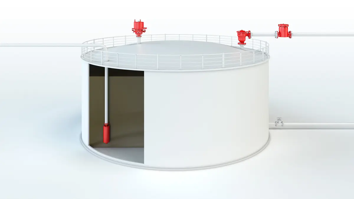
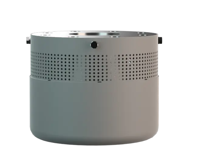
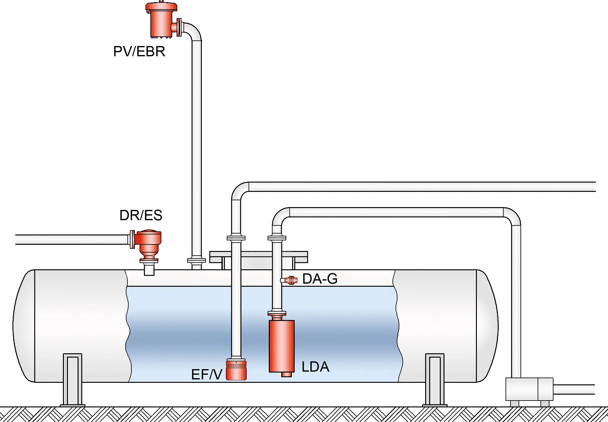
The PROTEGO® EF/V-IIB3 Detonation Detonation Explosion propagating at supersonic velocity and characterized by a shock wave. -Safe Foot Valve protects the suction line in a storage tank. The virtually maintenancefree device Device A device is a pipe component that influences the media flow by opening, closing, or partially shutting off the flow channel or by dividing or mixing the media flow. is installed at the end of the emptying line within the tank. During suction, the valve opens at an approximate under- pressure Pressure (gauge pressure) Pressure for which the value is equal to the algebraic difference between the absolute pressure and the atmospheric pressure. of 30 mbar / 12 inch W.C. When the pump is turned off, the device functions as a check valve Check valve A check valve allows flow of the operating media in one direction and prevents flow in the opposite direction. and prevents the line from emptying. This is very helpful when the pump is restarted.
Detonation-Proof Foot Valve Prevents Flame Transmission and Destruction
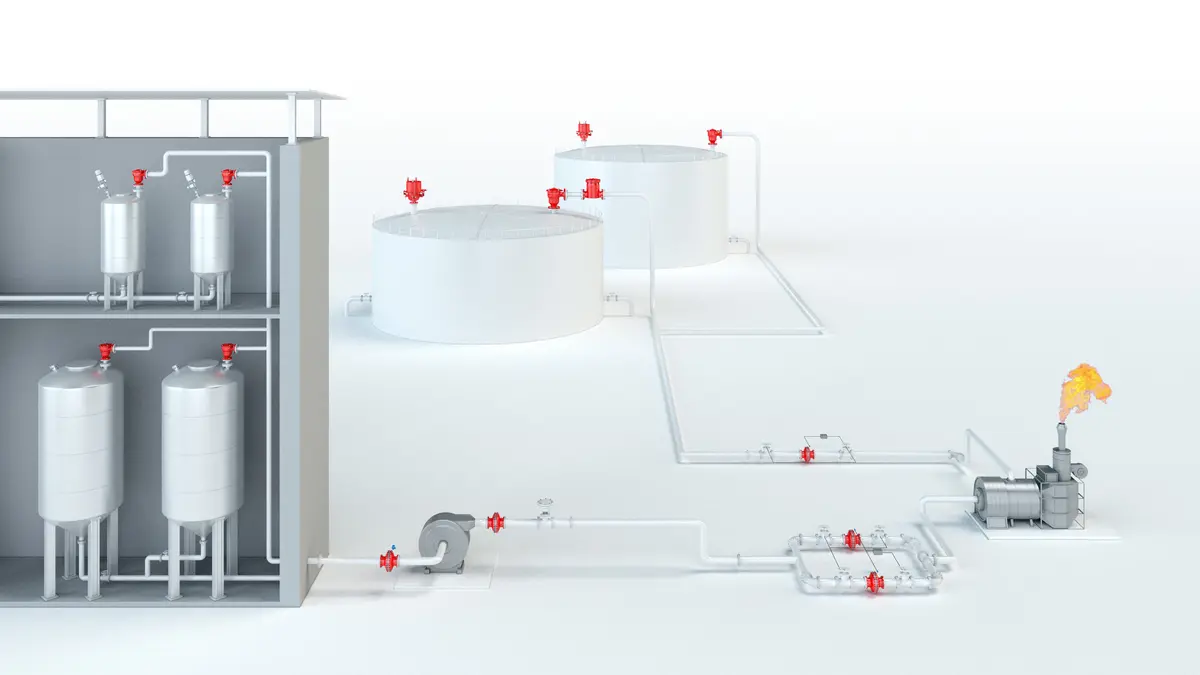
Combustible mixtures can form in filling and drain lines of storage containers that are not always filled with product Product Includes equipment, protective systems, devices, components and combinations of these. . Ignition of explosive atmospheres can lead to highly accelerated pipe deflagration Deflagration Explosion propagating at subsonic velocity. or detonations. The detonation-proof foot valve Foot valve A foot valve is a flame arrester designed to use the liquid product combined with a non-return valve to form a barrier against flame transmission. prevents the combustion from being transmitted into the tank and destroying it. The design of the foot valve ensures that the strainer is always filled with residual product. Together with the special valve design, this combination prevents flame flash back from the inside out.

For Explosion Group IIB3
The application limits for the device are a product vapor/air mixture temperature of up to +60°C / 140°F and an absolute pressure up to 1.1 bar / 15.9 psi. This covers all the possible operating conditions of empty lines for flammable liquids. The device protects against nearly all flammable liquids and is permitted for explosion Explosion Abrupt oxidation or decomposition reaction producing an increase in temperature, pressure, or in both simultaneously. group IIB3 (C MESG ≥ 0.65 mm). EU conformity according to the currently valid ATEX directive. Approvals according to other national/international regulations on request.
Dimensions
To select the nominal size Nominal size The nominal size is an alphanumeric designation of size for components in a piping system, used for reference purposes, comprising the letters DN followed by a dimensionless integer that is indirectly related to the physical size of the bore or outside diameter of the connections, expessed in millimeters. (DN), please use the flow capacity chart on the following pages
| DN | 25 / 1" | 32 / 1¼“ | 40 / 1½“ | 50 / 2" | 65 / 2½“ | 80 / 3" | 100 / 4" | 125 / 5" | 150 / 6" | 200 / 8" | 250 / 10" |
| a | 125 / 4.92 | 125 / 4.92 | 135 / 5.31 | 135 / 5.31 | 160 / 6.29 | 160 / 6.29 | 200 / 7.87 | 235 / 9.25 | 260 / 10.24 | 400 / 15.75 | 450 / 17.72 |
| b | 85 / 3.35 | 85 / 3.35 | 85 / 3.35 | 85 / 3.35 | 95 / 3.74 | 95 / 3.74 | 125 / 4.92 | 130 / 5.12 | 135 / 5.31 | 175 / 6.89 | 200 / 7.87 |
| c | 155 / 6.10 | 155 / 6.10 | 180 / 7.09 | 180 / 7.09 | 210 / 8.27 | 210 / 8.27 | 250 / 9.84 | 310 / 12.20 | 365 / 14.37 | 480 / 18.90 | 565 / 22.24 |
Dimensions in mm / inches
Material selection for housing
| Design | A | B | C | D |
| Housing Housing A housing is a solid shell, which surrounds a content, either protecting the content from external influences, or protecting the environment from the content. | Steel | Stainless Steel | Steel | Stainless Steel |
| Valve | Stainless Steel | Stainless Steel | Stainless Steel | Stainless Steel |
| Gasket (Valve) | PTFE | PTFE | PTFE | PTFE |
| Gasket (Housing) | FPM | FPM | PTFE | PTFE |
| Strainer | Stainless Steel | Stainless Steel | Stainless Steel | Stainless Steel |
Special materials upon request
Selection of explosion group
| MESG | Expl. Gr. (IEC / CEN) | Gas Group (NEC) |
| > 0,90 mm | IIA | D |
| ≥ 0,65 mm | IIB3 | C |
Special approvals upon request
Specification of max. operating temperature
| ≤ 60°C / 140°F | Tmaximum allowable operating temperature Operating temperature Temperature reached when the equipment is operating under design conditions. in °C |
| - | Designation |
higher operating temperatures upon request
Flange connection type
| EN 1092-1; Form B1 |
| ASME B16.5 CL 150 F.F. |
other connections upon request
Flow Capacity Chart
The volume flow V in m³/h was determined with water according to DIN EN 60534 at a temperature Tn = 20°C and an atmospheric pressure pn = 1,013 bar, kinematic viscosity v = 10-6 m²/s
To avoid electrostatic charge of flammable liquids the maximum flow is limited (refer to TRGS 727, CENELEC-Report CLC/TR 60079-32-1).