EB
Deflagration Flame Arrester, endurance burning proof, End-of-Line
Caractéristiques
Fonction et description
Protection Against Atmospheric Deflagration and Endurance Burning
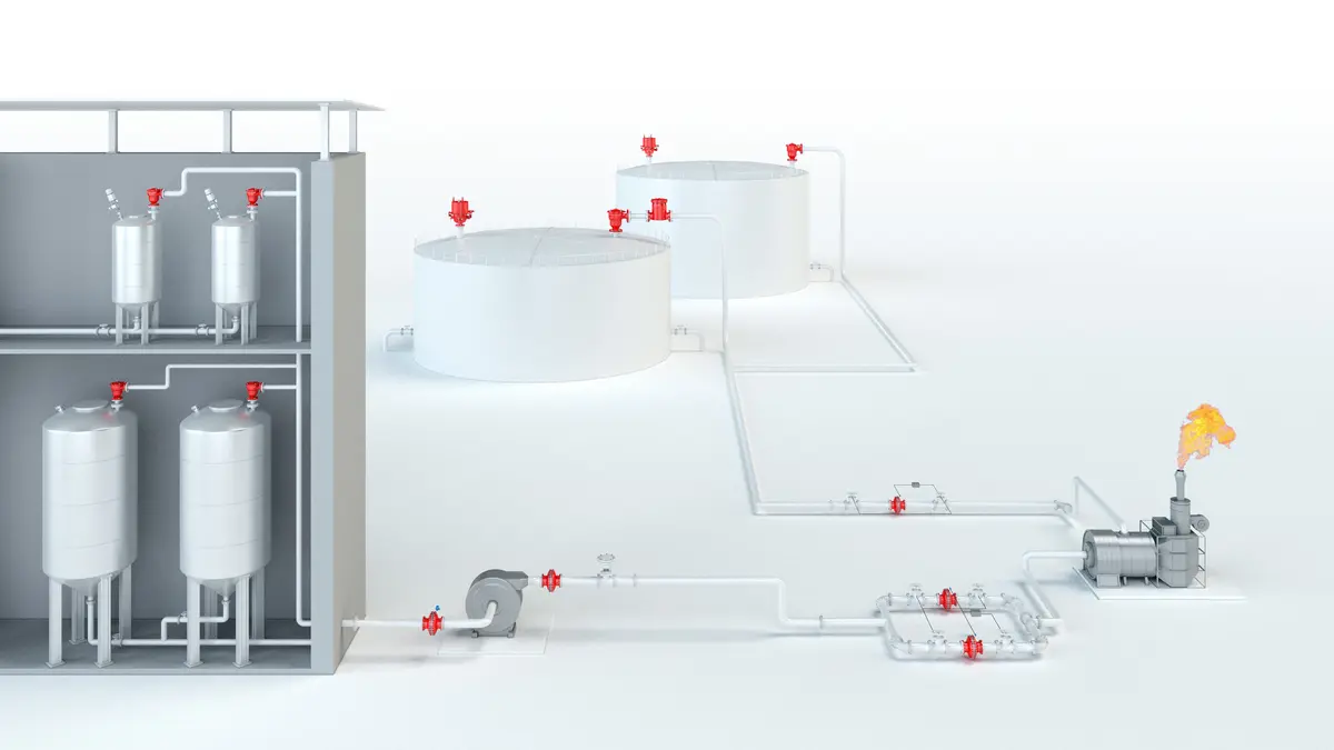
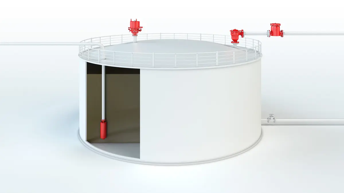
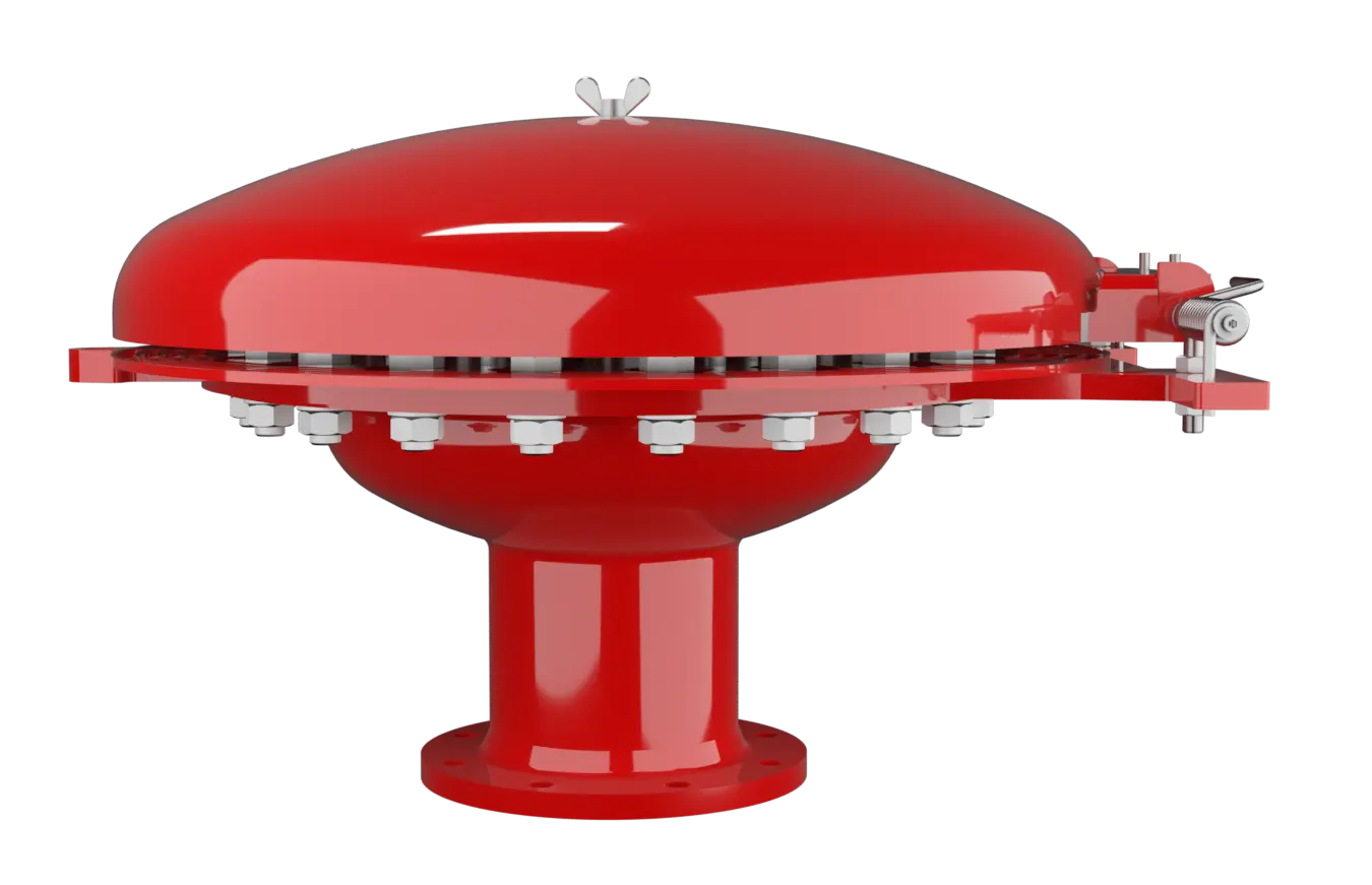
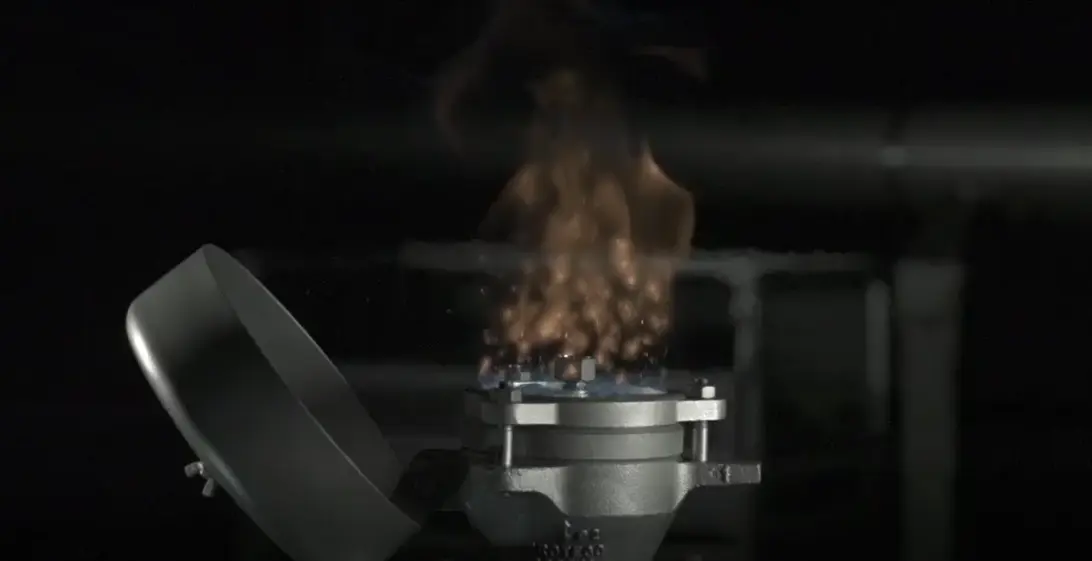
The PROTEGO® EB End-of-Line Deflagration Flame Arrester Arrête-flammes antidéflagration Flame arrester designed to prevent the transmission of a deflagration. It can be an end-of-line flame arrester or an in-line flame arrester. provides protection against atmospheric deflagration and long-lasting stabilized flames, called endurance burning Endurance burning Stabilized burning for an unlimited time. . The device Appareil A device is a pipe component that influences the media flow by opening, closing, or partially shutting off the flow channel or by dividing or mixing the media flow. is typically installed on vent lines of vessels and plant equipment which is not pressurized. The device prevents flame transmission from endurance burning or atmospheric deflagration into the vessel Récipient Container or structural envelope in which materials are processed, treated or stored. or plant.
Main Component – PROTEGO® Flame Arrester Unit
The PROTEGO® EB-IIA consists of the PROTEGO® Flame Arrester Unit (1) and the metal weather hood Capot de protection contre les intempéries A weather hood is a cover to protect the internal components of a device from environmental influences. (2). During normal operation, the metal weather hood is in a closed position. If a stabilized flame burns on the flame arrester element surface, the melting element Elément fusible The melting element is a component that consists of a housing with a lower and upper part. (3), located in a center position, will melt and let the spring Ressort A spring is a spiral of wire which returns to its original shape after it is pressed or pulled. -loaded weather hood move into the open position. The PROTEGO® Flame Arrester Unit consists of one or more FLAMEFILTER® (5), which are installed in a FLAMEFILTER® casing (4), a fixation element (6) and an insert ring (7).

For Explosion Group IIB and IIA
The FLAMEFILTER® gap size, height, and quantity depend on the device’s intended use. The PROTEGO® EB Series End-of-Line Deflagration Flame Arrester is available for substances from explosion group IIA and IIB (NEC group D and B). The standard design can be used with an operating temperature Operating temperature Temperature reached when the equipment is operating under design conditions. of up to +60°C / 140°F. Devices with special approval for higher temperatures are available upon request. EU conformity according to the currently valid ATEX directive. Approvals according to other national/international regulations on request.
Dimensions DN 25 - 150 for EB-IIA and IIB
To select the nominal size Diamètre nominal The nominal size is an alphanumeric designation of size for components in a piping system, used for reference purposes, comprising the letters DN followed by a dimensionless integer that is indirectly related to the physical size of the bore or outside diameter of the connections, expessed in millimeters. (DN), please use the flow capacity chart on the following page
| DN | 25 / 1" | 32 / 1¼“ | 40 / 1½“ | 50 / 2“ | 65 / 2½“ | 80 / 3“ | 100 / 4" | 125 / 5" | 150 / 6" |
| a | 218 / 8.58 | 218 / 8.58 | 218 / 8.58 | 218 / 8.58 | 218 / 8.58 | 353 / 13.90 | 353 / 13.90 | 353 / 13.90 | 353 / 13.90 |
| b | 113 / 4.45 | 113 / 4.45 | 113 / 4.45 | 113 / 4.45 | 113 / 4.45 | 113 / 4.45 | 113 / 4.45 | 113 / 4.45 | 113 / 4.45 |
| c | 232 / 9.13 | 232 / 9.13 | 232 / 9.13 | 232 / 9.13 | 232 / 9.13 | 306 / 12.05 | 306 / 12.05 | 306 / 12.05 | 306 / 12.05 |
| d | 222 / 8.74 | 222 / 8.74 | 222 / 8.74 | 222 / 8.74 | 222 / 8.74 | 355 / 13.98 | 355 / 13.98 | 355 / 13.98 | 355 / 13.98 |
| e | 217 / 8.54 | 217 / 8.54 | 217 / 8.54 | 217 / 8.54 | 217 / 8.54 | 322 / 12.68 | 322 / 12.68 | 322 / 12.68 | 322 / 12.68 |
| EB-IIA and IIB with cone / nozzle** | |||||||||
| DN | 50 / 2" | 80 / 3" | 100 / 4" | 150 / 6" | |||||
| DN2 | ≤50 / 2“ | ≤80 / 3“ | ≤100 / 4 | ≤150 / 6“ | |||||
| b* | 238 / 9.37 | 263 / 10.35 | 383 / 15.08 | 313 / 12.32 | |||||
| Dimensions DN 200 - 800 / 8“ - 32“ for EB-IIA | |||||||||
| DN | 200 / 8" | 300 / 12" | 400 / 16" | 500 / 20" | 600 / 24" | 800 / 32“ | |||
| a | 405 / 15.94 | 555 / 21.85 | 705 / 27.75 | 855 / 33.66 | 1005 / 39.57 | 1210 / 47.64 | |||
| b | 177 / 6.97 | 206 / 8.11 | 235 / 9.25 | 265 / 10.43 | 294 / 11.57 | 330 / 12.99 | |||
| c | 496 / 19.53 | 650 / 25.59 | 802 / 31.57 | 987 / 38.86 | 1137 / 44.76 | 1336 / 52.60 | |||
| d | 900 / 35.43 | 1200 / 47.24 | 1500 / 59.06 | 1820 / 71.65 | 2120 / 83.46 | 2525 / 99.41 | |||
| f | 450 / 17.72 | 600 / 23.62 | 750 / 29.53 | 920 / 36.22 | 1070 / 42.13 | 1270 / 50.00 | |||
| g | 51 / 2.01 | 80 / 3.15 | 109 / 4.29 | 138 / 5.43 | 167 / 6.57 | 204 / 8.03 | |||
| EB-IIA with cone / nozzle** | |||||||||
| DN | 200 / 8" | 300 / 12" | 400 / 16" | 500 / 20" | 600 / 24" | 800 / 32" | |||
| DN2 | ≤200 / 8“ | ≤300 / 12“ | ≤400 / 16“ | ≤500 / 20“ | ≤600 / 24“ | ≤800 / 32“ | |||
| b* | 401 / 15.94 | 456 / 17.95 | 535 / 21.06 | 614 / 24.17 | 693 / 27.28 | 830 / 32.68 |
Dimensions in mm / inches
** combinations (DN/DN2) please use the table on the following page
Combination (DN/DN2) for EB with cone
Flow capacity charts for EB-DN/DN2-IIA/IIB with cone upon request
| DN | 50 / 2“ | 80 / 3“ | 100 / 4“ | 150 / 6“ | 200 / 8“ | 300 / 12“ | 400 / 16“ | 500 / 20“ | 600 / 24“ | 800 / 32“ |
| DN2 | ||||||||||
| 20 / ¾“ | IIA / IIB | IIA / IIB | IIA / IIB | IIA / IIB | ||||||
| 25 / 1“ | IIA / IIB | IIA / IIB | IIA / IIB | IIA / IIB | ||||||
| 32 / 1¼" | IIA / IIB | IIA / IIB | IIA / IIB | IIA / IIB | ||||||
| 40 / 1½" | IIA / IIB | IIA / IIB | IIA / IIB | IIA / IIB | ||||||
| 50 / 2“ | IIA / IIB | IIA / IIB | IIA / IIB | IIA / IIB | IIA | |||||
| 65 / 2½“ | IIA / IIB | IIA / IIB | IIA / IIB | |||||||
| 80 / 3“ | IIA / IIB | IIA / IIB | IIA / IIB | IIA | IIA | |||||
| 100 / 4“ | IIA / IIB | IIA / IIB | IIA | IIA | ||||||
| 125 / 5“ | IIA / IIB | IIA | ||||||||
| 150 / 6“ | IIA / IIB | IIA | IIA | IIA | ||||||
| 200 / 8“ | IIA | IIA | IIA | IIA | IIA | |||||
| 250 / 10“ | IIA | IIA | IIA | |||||||
| 300 / 12“ | IIA | IIA | IIA | |||||||
| 350 / 14“ | IIA | IIA | ||||||||
| 400 / 16“ | IIA | IIA | IIA | |||||||
| 450 / 18“ | IIA | IIA | IIA | |||||||
| 500 / 20“ | IIA | IIA | ||||||||
| 600 / 24“ | IIA | |||||||||
| 700 / 28“ | IIA |
Material selection for housing
| Design | A | B |
| flange ring | Steel | Stainless Steel |
| Weather hood | Steel | Stainless Steel |
| cone / nozzle | Steel | Stainless Steel |
| Flame arrester unit Flame arrester unit Flame arrester casing with FLAMEFILTER® set. | A, B, C | B, C |
Special materials upon request
Material combinations of flame arrester unit
| Design | A | B | C |
| FLAMEFILTER® cage | Steel | Stainless Steel | Stainless Steel / Hastelloy |
| FLAMEFILTER® | Stainless Steel | Stainless Steel | Hatselloy |
| Spider ring | Steel | Stainless Steel | Stainless Steel / Hastelloy |
Special materials upon request
Selection of explosion group
| MESG | Expl. Gr. (IEC / CEN) | Gas Group (NEC) |
| > 0,90 mm | IIA | D |
| ≥ 0,50 mm | IIB | B |
Special approvals upon request
Flange connection type
| EN 1092-1 (without cone); EN 1092-1; Form B1 (with cone / nozzle) |
| ASME B16.5 (without cone); ASME B16.5 CL 150 R.F. (with cone / nozzle) |
other types upon request
Design Types and Specifications
There are three different designs:Special designs available on request
Flow Capacity Chart
Remark: Flow capacity charts for EB-DN/DN2-IIA/IIB with cone upon request
The flow capacity charts have been determined with a calibrated and TÜV certified flow capacity test rig. Volume flow V in (m³/h) and CFH refer to the standard reference conditions of air ISO 6358 (20°C, 1bar). For conversion to other densities and temperatures refer to Sec. 1: “Technical Fundamentals”.