DA-SB-EO-P1,1
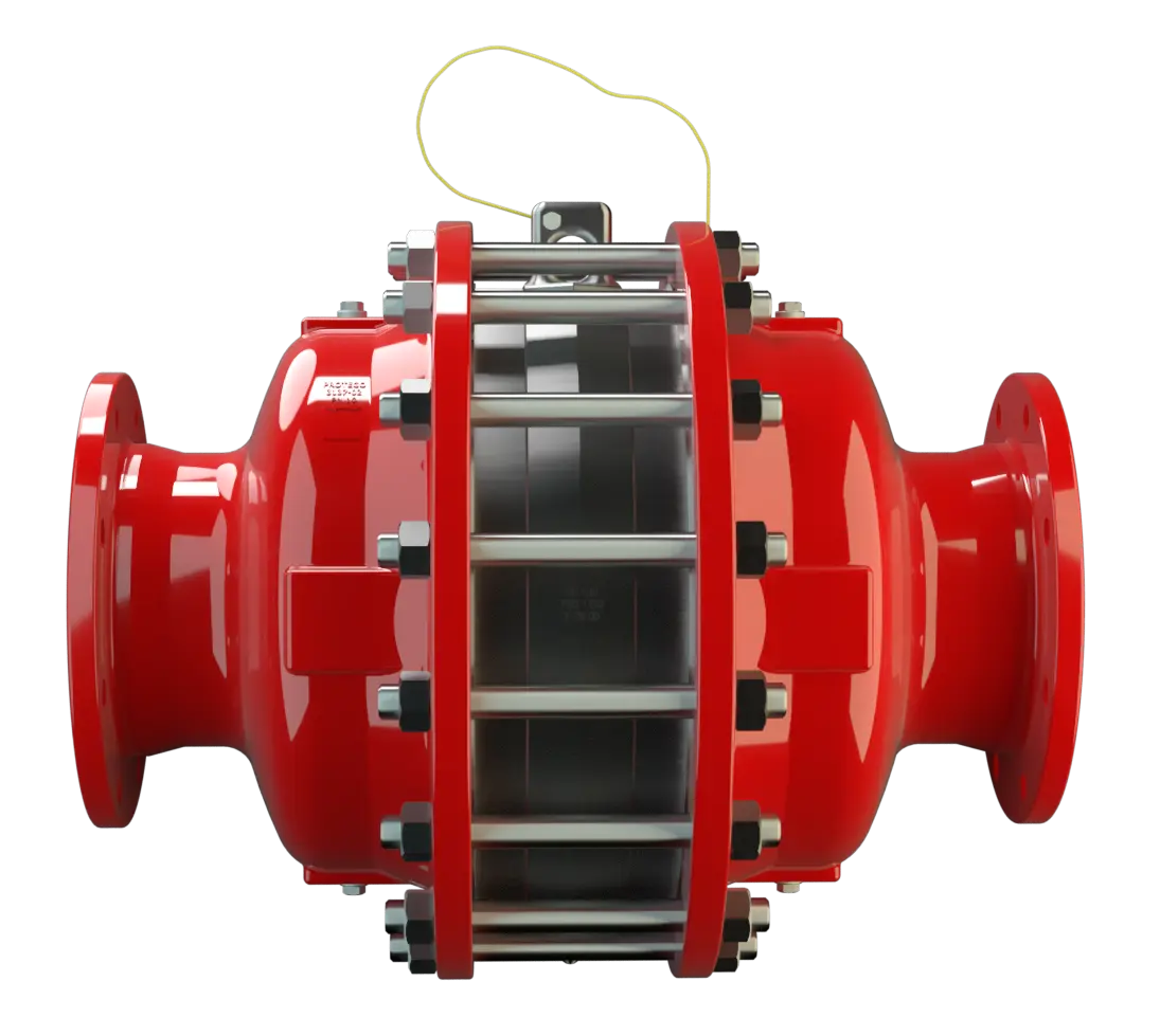
In-Line Detonation Flame Arrester for stable detonations and deflagrations in a straight through design with shock tube, bidirectional
Caractéristiques
Fonction et description
In-Line Detonation Flame Arresters with Shock Wave Guide Tube Effect
The In-Line Detonation Detonation Explosion, die sich mit Überschallgeschwindigkeit fortpflanzt, gekennzeichnet durch eine Stoßwelle. Flame Arresters Type PROTEGO® DA-SB-EO are the newest generation of Flame Arresters. Based on flow and explosion dynamic calculations as well as decades of field tests, a product line was developed that offers minimum pressure losses with maximum safety. The Flame Arrester uses the Shock Wave Guide Tube Effect (SWGTE) to separate the flame front and shock wave. The result is an in-line detonation arrester without a classic shock absorber, which minimizes the use of FLAMEFILTER® discs.
Main Component – PROTEGO® Flame Arrester Unit
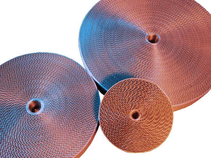
The devices are symmetrical and offer bi-directional flame arresting for deflagrations and stable detonations for Ethylene oxide/air-mixtures. The arrester essentially consists of two housing parts with an integrated shock tube (1) and the PROTEGO® Flame Arrester Unit (2) in the center. The PROTEGO® Flame Arrester Unit is modular and consists of several FLAMEFILTER® discs (3) and spacers firmly held in a FLAMEFILTER® casing.

Many Individual Certifications
The standard design can be used with an operating temperature of up to +60°C / 140°F and an absolute operating pressure up to 1.1 bar / 15.9 psi. EU conformity according to the currently valid ATEX directive.
Dimensions
To select nominal width/nominal size (NG/DN) - combination, please use the flow capacity charts on the following pages
| NG | 150 / 6“ | 150 / 6“ | 200 / 8“ | 300 / 12“ | 400 / 16“ |
| DN | ≤50 / 2" | 65, 80 / 2½", 3" | ≤100 / 4" | ≤150 / 6" | ≤200 / 8" |
| a | 285 / 11.22 | 285 / 11.22 | 340 / 13.39 | 445 / 17.52 | 565 / 22.24 |
| b | 400 / 15.75 | 400 / 15.75 | 500 / 19.69 | 638 / 25.12 | 700 / 27.56 |
| c | 500 / 19.69 | 500 / 19.69 | 520 / 20.47 | 570 / 22.44 | 620 / 24.41 |
Dimensions in mm / inches
Material selection for housing
| Design | A | B | C |
| Housing | Steel | Stainless Steel | Hastelloy |
| Heating jacket (DA-SB-(T)-H-...EO) | Steel | Stainless Steel | Stainless Steel |
| Gasket | PTFE | PTFE | PTFE |
| Flame arrester unit | A, B | B, C, D | D |
The housing is also available in carbon steel with an ECTFE coating.
Special materials upon request
Material combinations of flame arrester unit
| Design | A | B | C | D |
| FLAMEFILTER® cage | Steel | Stainless Steel | Stainless Steel | Hastelloy |
| FLAMEFILTER®* | Stainless Steel | Stainless Steel | Hastelloy | Hastelloy |
| Spacer | Stainless Steel | Stainless Steel | Hastelloy | Hastelloy |
*the FLAMEFILTER® are also avail- able in the materials Tantalum, Inconel, Copper, etc. when the listed housing and cage materials are used.
Special materials upon request
Selection of explosion group
| MESG | Expl. Gr. (IEC / CEN) | Gas Group (NEC) |
| ≥ 0,59 mm | EO | EO |
Special approvals upon request
Selection of max. operating pressure
| DN | ≤50 / 2" | 65, 80 / 2½", 3" | ≤100 / 4" | ≤150 / 6" | ≤200 / 8" |
| NG | 150 / 6'' | 150 / 6'' | 200 / 8'' | 300 / 12'' | 400 / 16'' |
| Pmax | 1,1 / 15.9 | 1,1 / 15.9 | 1,1 / 15.9 | 1,1 / 15.9 | 1,1 / 15.9 |
Pmax = maximum allowable operating pressure in bar / psi absolut
in-between size up to Pmax upon request
*capacity charts upon request
Specification of max. operating temperature
| ≤ 60°C / 140°F | Tmaximum allowable operating temperature in °C |
higher operating temperatures upon request
Flange connection type
| EN 1092-1; Form B1 |
| ASME B16.5 CL 150 R.F. |
other connections upon request
Design Types and Specifications
There are four different designs available:Additional special arresters upon request
*Resistance thermometer for device group II, category (1) 2 (GII cat. (1) 2)
Flow Capacity Chart
The flow capacity charts have been determined with a calibrated and TÜV certified flow capacity test rig. Volume flow V in (m³/h) and CFH refer to the standard reference conditions of air ISO 6358 (20°C, 1bar). For conversion to other densities and temperatures refer to Sec. 1: “Technical Fundamentals”.