Caractéristiques
Fonction et description
Automatic Venting Valves for Floating Roof Tanks
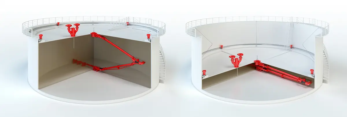
PROTEGO® Lift Lift Lift is the actual travel of the valve pallet from the main valve out of the closed position. -Actuated Vent Valves Type AL-DK-D provide automatic venting of floating roof Floating roof A floating roof is the roof of a tank that is fitted with floating chambers (pontoons) and lies on top of the liquid. tanks when the floating roof is lowered onto its supports and the tank is either drained or refilled. When the floating roof is in its lowest position, the valve is forced to open through lift actuation, which prevents inadmissible vacuum Vacuum Vacuum is the pressure in an enclosed space that is lower than the ambient pressure. during final draining or inadmissible pressure Pressure (gauge pressure) Pressure for which the value is equal to the algebraic difference between the absolute pressure and the atmospheric pressure. during refilling.
Design of Valves
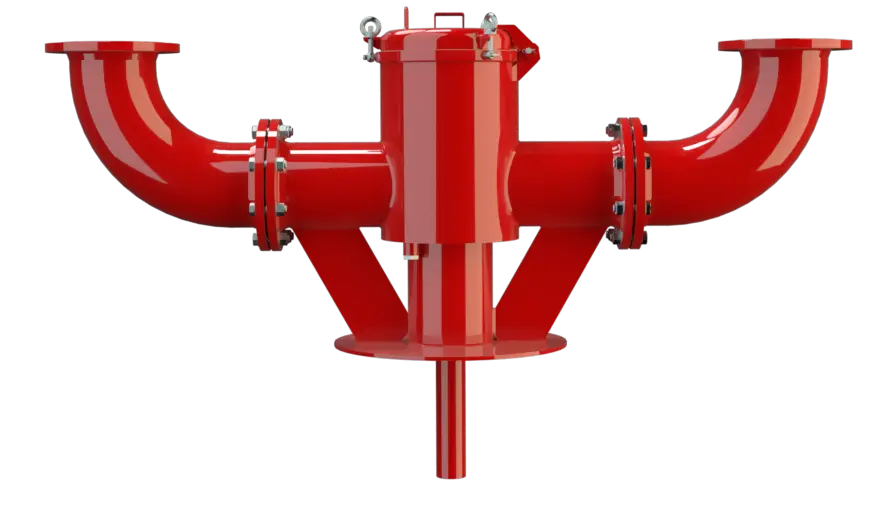
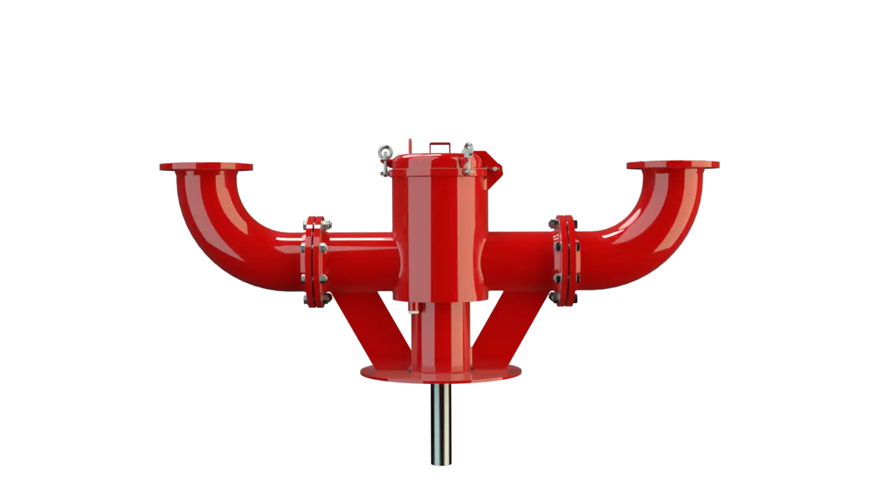
The PROTEGO® AL-DK-D valve consists of a housing Housing A housing is a solid shell, which surrounds a content, either protecting the content from external influences, or protecting the environment from the content. (1) with a sheet metal panel to be welded onto the floating roof or a flange for mounting on a mating flange, two or four flanged connection nozzles (2) for installation of vent caps, cover (3), lift (4) including valve disc (5), lift pipe (6), and the condensate drain valve (7) which can be designed to be flame transmission proof. The condensate drain is sealed by a flat gasket attached to the valve disk (5). The cover (3) is sealed by a sealing cord Sealing cord A sealing cord is a synthetic cord with a circular or square profile. It is used to seal off components. (8).
Dimensions for Different Floating Roof Heights
As the lowest position of the floating roof varies for operation and assembly, specify the dimensions h1 and h2: h1: Distance between the lower edge of the connection of the equipment Equipment Machines, appliances, fixed or mobile devices, control parts and accessories, and warning and prevention systems, whether separate or combined, intended for the generation, transfer, storage, measurement, control, and conversion of energy, and for the processing of materials, which have their own potential source of ignition and may cause an explosion. and the tank bottom at the lowest level of the floating roof in the operating position (operating position with an empty tank). h2: Distance between the lowest level of the floating roof in the maintenance Maintenance Combination of all technical and administrative actions, including supervision actions, intended to maintain or restore a unit in working order. position and the lowest level of the floating roof in the operating position (operating position with an empty tank).
Conversion of Floating Roof Supports and Extension of the Plunger
If the floating roof supports are changed from operating position to maintenance position, the lift has to be extended as well. This is done with an adjustable locking pin that is secured with a split pin. The valve is not flame transmission proof. Based on a hazard analysis with regard to material selection and function, the valves have no potential ignition sources. As a result, they are not subject to the European Explosion Explosion Abrupt oxidation or decomposition reaction producing an increase in temperature, pressure, or in both simultaneously. Protection Directive (ATEX) when used in explosive atmospheres.
Combined With Atmospherically Deflagration and Endurance Burning Proof Vent Caps
Lift-actuated vent valves PROTEGO® AL-DK-D can be combined with atmospherically deflagration Deflagration Explosion propagating at subsonic velocity. -proof and endurance burning Endurance burning Stabilized burning for an unlimited time. -proof vent caps.
Dimensions
| AL-DK-D | AL-DK-D-4 | |||
| DN1 | 200 / 8" | 200 / 8" | 200 / 8" | 200 / 8" |
| DN2 | 150 / 6" | 200 / 8" | 150 /6" | 200 / 8" |
| a | 350 / 13.78 | 350 / 13.78 | 350 / 13.78 | 350 / 13.78 |
| b | 905-1580 / 35.63-62.02 | 830-1580 / 32.68-62.02 | 689-1950 / 27.13-76.77 | 689-1950 / 27.13-76.77 |
| c | 870 / 34.25 | 870 / 34.25 | 870 / 34.25 | 870 / 34.25 |
| d | 600 / 23.62 | 600 / 23.62 | 600 / 23.62 | 600 / 23.62 |
| e | 415 / 16.34 | 415 / 16.34 | 415 / 16.34 | 415 / 16.34 |
| f | 370 / 14.57 | 370 / 14.57 | 370 / 14.57 | 370 / 14.57 |
| g | 460 / 18.11 | 460 / 18.11 | 460 / 18.11 | 460 / 18.11 |
| x | 974-1950 / 38.35-76.77 | 974-1950 / 38.35-76.77 | ||
| Weight (kg)* | max. 254 | max. 277 | max. 392 | max. 489 |
Dimensions in mm / inches
* The dimensions and weight vary depending on the type of endurance burning flame arrester Flame arrester Device fitted to the opening of an enclosure, or to the connecting pipe work of a system of enclosures, and whose intended function is to allow flow but prevent the transmission of a flame. .
Material
| Housing | Steel |
| Valve guide | Stainless Steel |
| Gasket | FPM |
Special materials upon request
Flange connection type
| EN 1092-1; Form B1 | andere Anschlüsse auf Anfrage |
| ASME B16.5 CL 150 R.F. |
Other types upon request
Data Necessary for Specification
Stored product Product Includes equipment, protective systems, devices, components and combinations of these. Tank diameter (m or ft)Tank diameter (m or ft)
Tank height (m or ft)
Support height h1 (operating position with empty tank)
Support height h2 (lifted assembly position)
Maximum allowable tank pressure Tank pressure Tank pressure is the pressure within a tank. pT (mbar or inch W.C.)
Pump rate (m³/h or CFH)
Selection and Design
The required quantity and nominal size Nominal size The nominal size is an alphanumeric designation of size for components in a piping system, used for reference purposes, comprising the letters DN followed by a dimensionless integer that is indirectly related to the physical size of the bore or outside diameter of the connections, expessed in millimeters. DN will be defined based on the calculated flow rate from the thermal venting and pumprate in lowest floating roof position (Nm³/h or CFH) and based on the maximum acceptable tank pressure pT (mbar / inch W.C.) according to the flow capacity charts. Special models are available on request.Flow rates and pressure losses of vent caps PROTEGO® EB or PROTEGO® BE/HR-400 have additionally to be taken into account according to the appropriate charts in the relevant data sheetsor operating instructions.Design Types and Specifications
Two designs are available:Flow Capacity Chart
The flow capacity charts have been determined with a calibrated and TÜV certified flow capacity test rig. Volume flow V in (m³/h) and CFH refer to the standard reference conditions of air ISO 6358 (20°C, 1bar). For conversion to other densities and temperatures refer to Sec. 1: “Technical Fundamentals”.
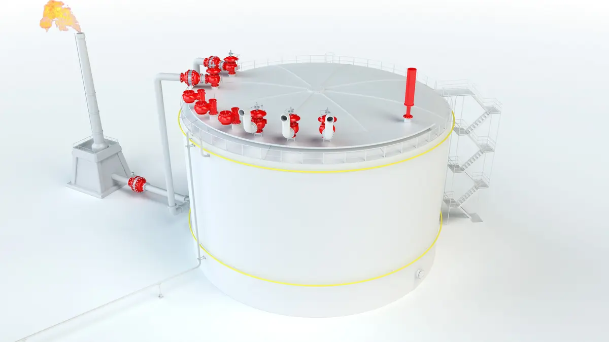
Application Example for PROTEGO® AL-DK-D
Lift-actuated vent valves of type PROTEGO® AL-DK-D can be combined with vent caps type PROTEGO® BE/HR-400 or PROTEGO® EB .