Características
Função e descrição
Highly Developed Pressure Relief Valve
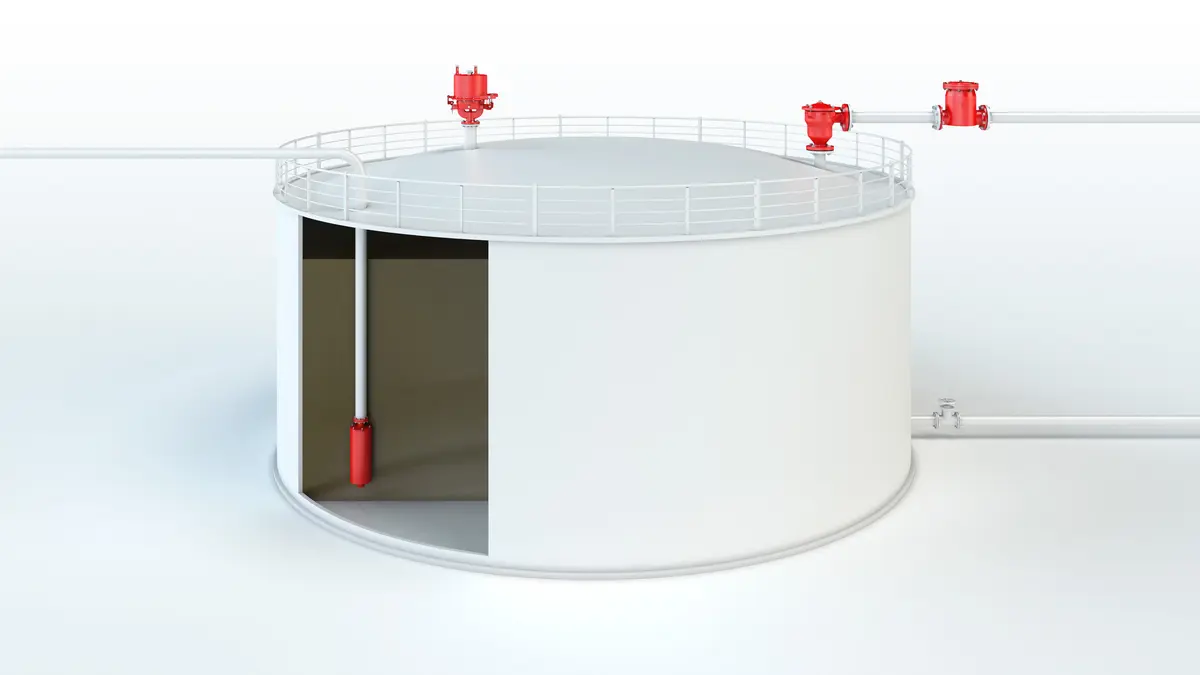
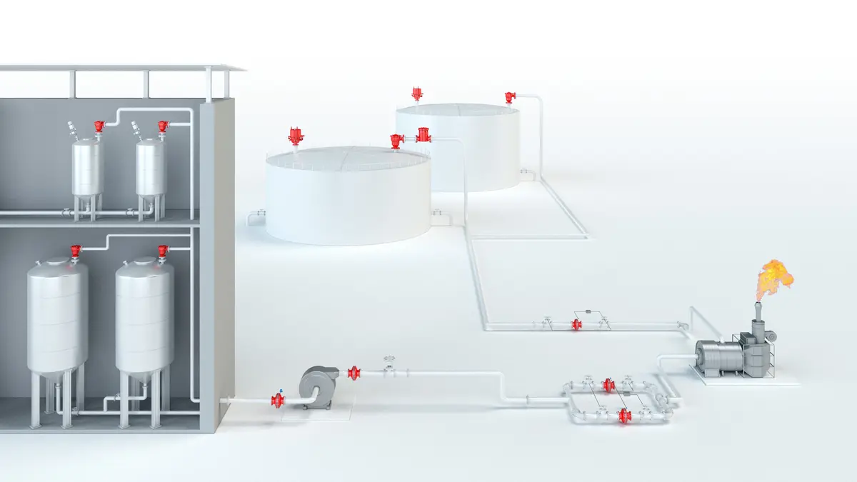
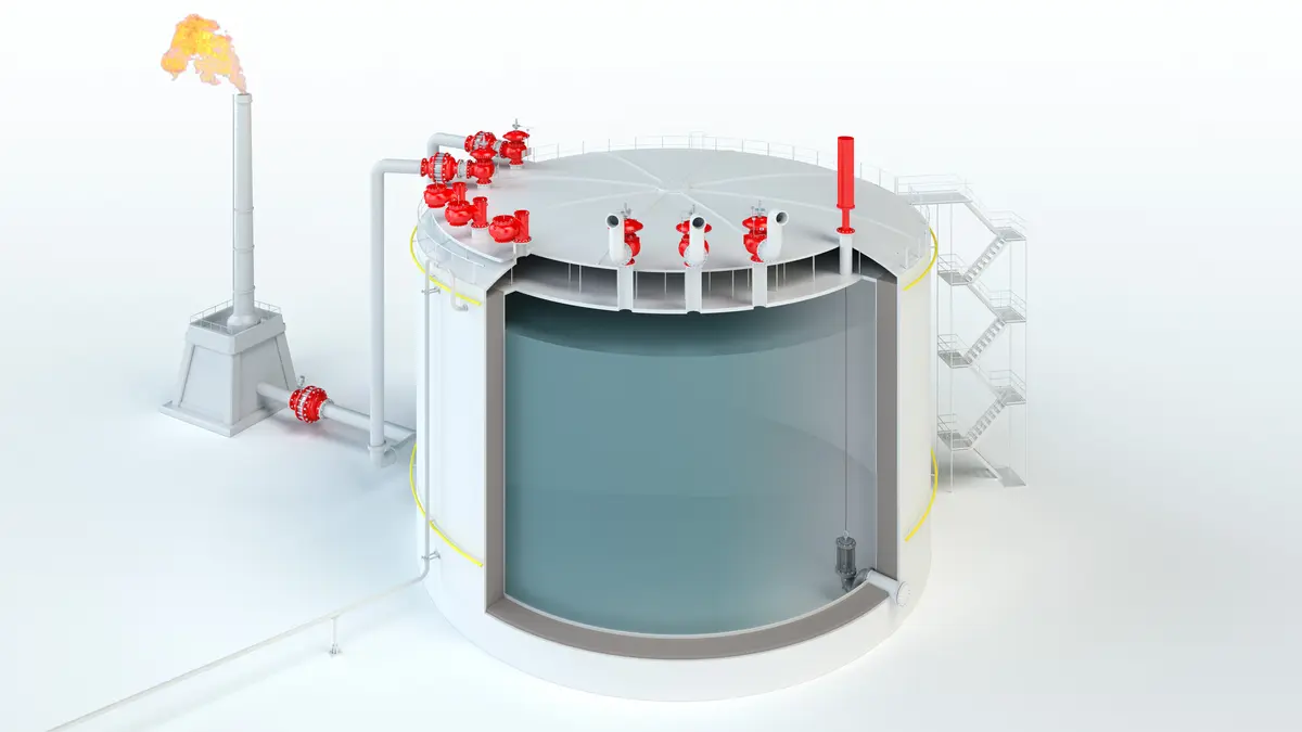
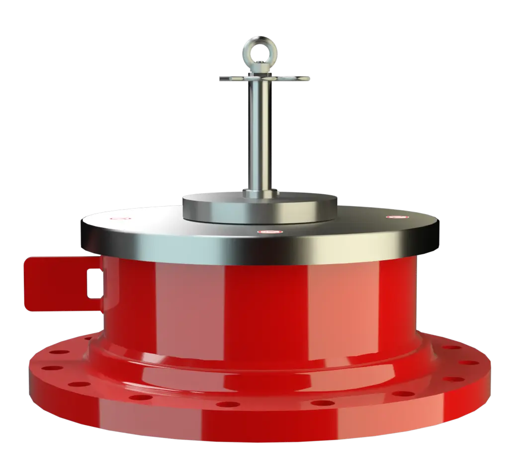
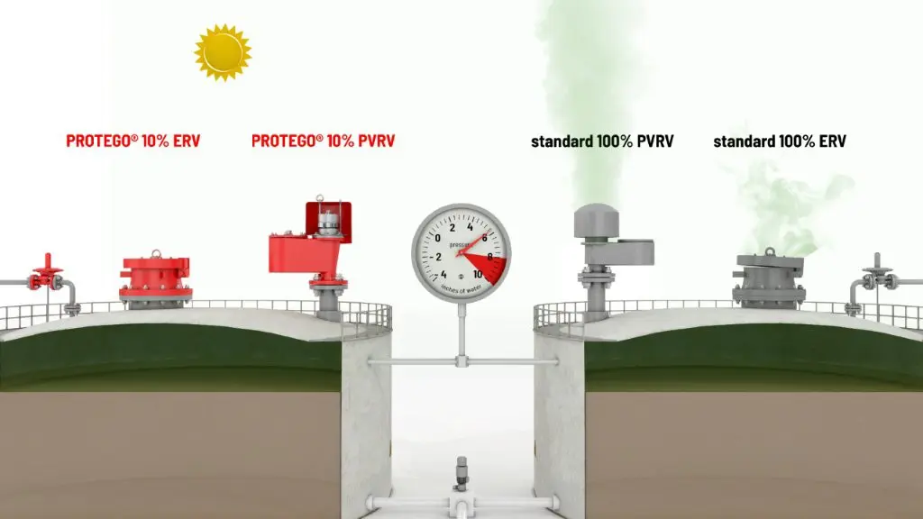
The PROTEGO® Type ER-V-LP valve is a sophisticated pressure relief valve Soupape de surpression Valve designed to open and relieve excess pressure and to reclose and prevent the further flow of fluid after normal conditions have been restored. for applications in which a high flow efficiency is of the essence. It is primarily used as an emergency pressure relief valve on storage tanks, vessels, silos, and process engineering equipment. It offers reliable protection against excessive overpressure Surpression Overpressure refers to an increase in pressure in a system or vessel above the normal operating pressure. and prevents excessive product loss at pressures as high as close to the set pressure Pression de réponse Set pressure is the gauge pressure at the device inlet at which the relief device is set to start opening under service conditions. . It is designed to release particularly large quantities to prevent the vessel Récipient Container or structural envelope in which materials are processed, treated or stored. from rupturing in an emergency case.
Patented Valve Pallet Technology
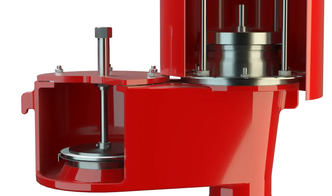
The valve will start to open as soon as the set pressure is reached and only requires a 10% pressure increase or opening pressure differential until full lift Course Lift is the actual travel of the valve pallet from the main valve out of the closed position. . Continuous investments in and a commitment to research and development have enabled PROTEGO® to develop a New Valve Pallet Technology for which a patent has been granted. This Patented Valve Pallet Technology enables the typical safety valve characteristics to be applied to low pressure ranges while also maintaining a low leakage rate. Adopting this new patented Valve Pallet Technology permits the valve to be set to just 10% below the maximum allowable working pressure of the tank and still vent the required flow.
Advanced Manufacturing Technology
Due to the sophisticated manufacturing technology, the tank pressure Pression de la cuve Tank pressure is the pressure within a tank. is maintained up to the set pressure, with a tightness that is far above the common standards. Once the excess pressure is released, the valve re-seats and seals tight again.
Tabela de dimensões
Para escolher o diâmetro nominal (DN), veja o diagrama de vazão da página seguinte
| DN | 200 / 8" | 250 / 10" | 300 / 12" | 350 / 14" | 400 / 16" | 450 / 18" | 500 / 20" | 600 / 24" | 700 / 28" |
| a | 343 | 406 | 483 | 533 | 597 | 635 | 699 | 813 | 837 |
| b | 378 | 399 | 409 | 440 | 455 | 464 | 481 | 556 | 571 |
Dimensões em mm
Seleção do material
| Execução | A | B |
| Corpo | Aço | Aço inoxidável |
| Sedes de válvulas | Aço inoxidável | Aço inoxidável |
| Obturador da válvula | Aço inoxidável | Aço inoxidável |
| Vedação | Aço inoxidável | Aço inoxidável |
Materiais especiais sob solicitação
Tipo de conexão flangeada
| EN 1092-1; Form B1 |
| ASME B16.5 CL 150 R.F. |
Outras conexões sob solicitação
Versão e especificação
O obturador da válvula é calibrado por peso. Pressões de ajuste mais altas são realizadas geralmente com alavanca (veja ER/VH, ER/V) ou com válvula calibrada por mola (veja ER/V-F).Outros dispositivos especiais sob solicitação
Settings
| DN 200 to DN 300 | +3.4 mbar | +40 mbar |
| +1.4 inch W.C. | +16 inch W.C. | |
| DN 350 to DN 700 | +3.4 mbar | +25 mbar |
| +1.4 inch W.C. | +10 inch W.C. |
Ajustes de pressões mais altos, veja tipo ER/V, ER/VH e ER/V-F.
Diagrama de vazão
Este diagrama de vazão foi determinado em uma bancada de medição de vazão calibrada e certificada pela TÜV. A vazão V em m³/h se refere ao estado técnico padrão de ar, conforme ISO 6358 (20°C, 1bar). Para conversão em outras densidades e temperaturas, veja o cap. 1: Bases técnicas.