DR/SBW
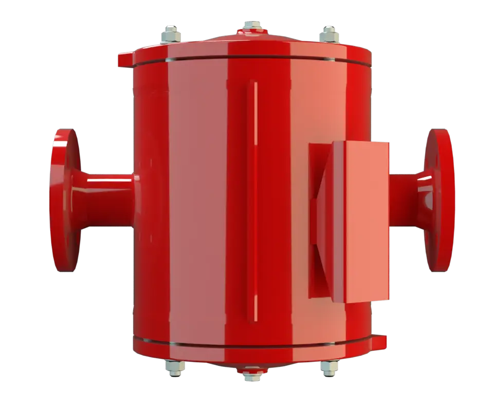
In-Line Detonation Flame Arrester for stable detonations and deflagrations in a straight through design with shock absorber, bidirectional
Características
Função e descrição
Maintenance-Friendly In-Line-Detonation Flame Arrester
In the development of the PROTEGO® DR/SBW In-Line Detonation Flame Arrester, special effort was made to ease future maintenance of the Flame Arresters. The PROTEGO® Flame Arrester Unit (5) can be removed and cleaned within moments without having to disassemble the piping. The effective shock absorber Amortisseur de choc A shock absorber is a device that reduces the kinetic energy of a detonation. of the device Appareil A device is a pipe component that influences the media flow by opening, closing, or partially shutting off the flow channel or by dividing or mixing the media flow. and elaborate housing Corps A housing is a solid shell, which surrounds a content, either protecting the content from external influences, or protecting the environment from the content. geometry reduces the number of FLAMEFILTER® discs to a minimum.
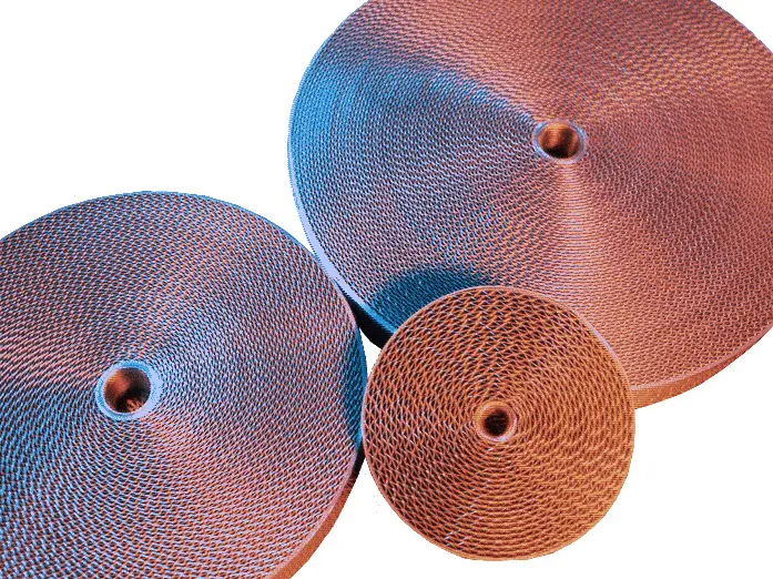
Main Component – PROTEGO® Flame Arrester Unit
The device is symmetrical and offers bidirectional flame arresting protecting from stable detonations and deflagrations. The Flame Arrester consists of a double-jacket housing (1) with two integrated shock absorbers (2) with the PROTEGO® Flame Arrester Unit in the center. The PROTEGO® Flame Arrester Unit consists of several FLAMEFILTER® discs (4) and spacers firmly held in a FLAMEFILTER® cage Cage d'éléments arrête-flammes The FLAMEFILTER® cage is a housing for a FLAMEFILTER® set. (3). The number of FLAMEFILTER® discs and their gap size depends on the arrester‘s conditions of use. By indicating the operating parameters such as the temperature, pressure and explosion group and the composition of the fluid, the optimum In-Line Detonation Flame Arrester can be selected. The PROTEGO® DR/SBW Series of Flame Arresters is available for explosion groups IIA to IIB3 (NFPA group D to C MESG ≥ 0.65 mm).

Many Individual Certifications
The standard design is approved at an operating temperature Operating temperature Temperature reached when the equipment is operating under design conditions. up to +60°C / 140°F and an absolute operating pressure Pression de service Operating pressure is the pressure existing at normal operating conditions within the system being protected. acc. to table 3. Devices with special approvals can be obtained for higher pressures and higher temperatures upon request. Type-approved in accordance with the current ATEX Directive and as well as other international standards.
Tabela de dimensões
Para selecionar o diâmetro nominal (DN), utilize os diagramas de vazão nas páginas seguintes
| DN | 50 / 2" | 80 / 3" | 100 / 4" | 150 / 6" | 200 / 8" | 250 / 10" | 300 / 12" | 350 / 14" | 400 / 16" |
| NG | 150 / 6" | 150 / 6" | 200 / 8" | 300 / 12" | 500 / 20" | 500 / 20" | 600 / 24" | 700 / 28" | 800 / 32" |
| a | 225 / 8.86 | 225 / 8.86 | 275 / 10.83 | 350 / 13.78 | 550 / 21.65 | 550 / 21.65 | 725 / 28.54 | 800 / 31.50 | 825 / 32.48 |
| b | 210 / 8.27 | 210 / 8.27 | 220 / 8.66 | 290 / 11.42 | 525 / 20.67 | 525 / 20.67 | 590 / 23.23 | 655 / 25.78 | 725 / 28.54 |
| b1* | 325 / 12.80 | 325 / 12.80 | 360 / 14.17 | 475 / 18.70 | 835 / 32.87 | 835 / 32.87 | 960 / 37.80 | 1075 / 42.32 | 1215 / 47.83 |
| c | 395 / 15.55 | 395 / 15.55 | 410 / 16.14 | 475 / 18.70 | 630 / 24.80 | 630 / 24.80 | 700 / 27.56 | 765 / 30.12 | 835 / 32.87 |
| c1* | 450 / 17.72 | 450 / 17.72 | 465 / 18.31 | 530 / 20.87 | 730 / 28.74 | 730 / 28.74 | 800 / 31.50 | 865 / 34.06 | 935 / 36.81 |
| d | 275 / 10.83 | 275 / 10.83 | 325 / 12.80 | 460 / 18.11 | 840 / 33.07 | 840 / 33.07 | 1000 / 39.37 | 1150 / 45.28 | 1250 / 49.21 |
Dimensões em mm
* b1 dismantling dimension for servicing
c1 dismantling dimension for servicing (
temperature sensor
Sonde de température
Temperature sensor for monitoring the temperature.
)
Seleção do material do corpo
| Versão | A | B | C |
| Corpo | Aço | Aço inoxidável | Hastelloy |
| Camisa de aquecimento (DR / SBW-H-..) | Aço | Aço inoxidável | Edelstahl |
| Tampa com absorvedor de choque | Aço | Aço inoxidável | Hastelloy |
| Vedação | FPM* | PTFE | PTFE |
| Conjunto abafador de chamas | A | C, D | E |
* para equipamentos em caso de aplicação com temperaturas elevadas a partir de 150 °C (T150), vedações em PTFE.
Materiais especiais sob solicitação
Combinações de material do conjunto abafador de chamas
| Versão | A | C | D | E |
| Armação do jogo de FLAMEFILTER® | Aço | Aço inoxidável | Aço inoxidável | Hastelloy |
| FLAMEFILTER® | Aço inoxidável | Aço inoxidável | Hastelloy | Hastelloy |
| Espaçadores | Aço inoxidável | Aço inoxidável | Hastelloy | Hastelloy |
* os FLAMEFILTER® também podem ser fornecidos em tântalo, Inconel, cobre, etc. em caso de utilização dos materiais do corpo ou da armação listados.
Materiais especiais sob solicitação
Seleção do grupo de explosão
| MESG | Gr. expl. (IEC / CEN) | Grupo gás (NEC) |
| > 0,90 mm | IIA | D |
| ≥ 0,65 mm | IIB3 | C |
Aprovações especiais sob solicitação
Seleção da pressão máx. de trabalho
| DN | 50 / 2" | 80 / 3" | 100 / 4" | 150 / 6" | 200 / 8" | 250 / 10" | 300 / 12" | 350 / 14" | 400 / 16" | ||
| NG | 150 / 6" | 150 / 6" | 200 / 8" | 300 / 12" | 500 / 20" | 500 / 20" | 600 / 24" | 700 / 28" | 800 / 32" | ||
| Expl. Gr. | IIA | Pmax | 4 | 4 | 3 | 3 | 1,6 | 1,6 | 1,1 | 1,1 | 1,1 |
| Expl. Gr. | IIB3 | Pmax | 1,7 | 1,7 | 1,7 | 1,7 | 1,2 | 1,2 | 1,1 | 1,1 | 1,1 |
Pmáx. = pressão de trabalho máxima admissível em bar absoluta, pressão de trabalho mais elevada sob solicitação
Indicação da temperatura máx. de trabalho
| ≤ 60°C / 140°F | Ttemperatura máxima de trabalho admissível em °C |
| - | Designation |
temperaturas de trabalho mais elevadas, sob solicitação
Tipo de conexão flangeada
| EN 1092-1; Form B1 |
| ASME B16.5 CL 150 R.F. |
Outras conexões sob solicitação
Versão e especificação
Estão disponíveis quatro versões:Additional special flame arresters upon request
*Resistance thermometer for device group II, category (1) 2 (GII cat. (1) 2)
Diagrama de vazão
Este diagrama de vazão foi determinado em uma bancada de medição de vazão calibrada e certificada pela TÜV. A vazão V em m³/h se refere ao estado técnico padrão de ar, conforme ISO 6358 (20°C, 1bar). Para conversão em outras densidades e temperaturas, veja o cap. 1: Bases técnicas.