LDA
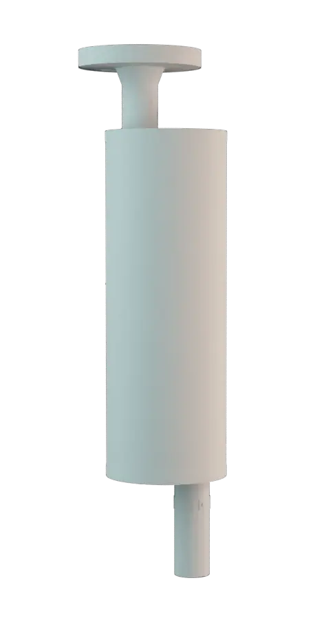
Liquid Detonation Flame Arrester for filling lines - internal installation
Características
Función y descripción
Prevention of Flame Spread in Tank During Ignition
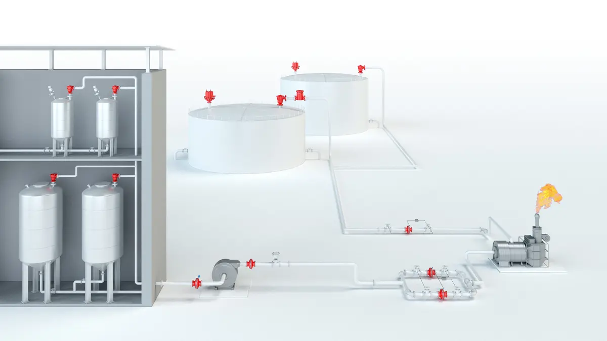
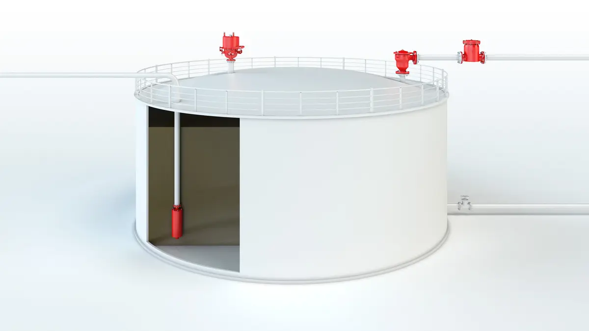
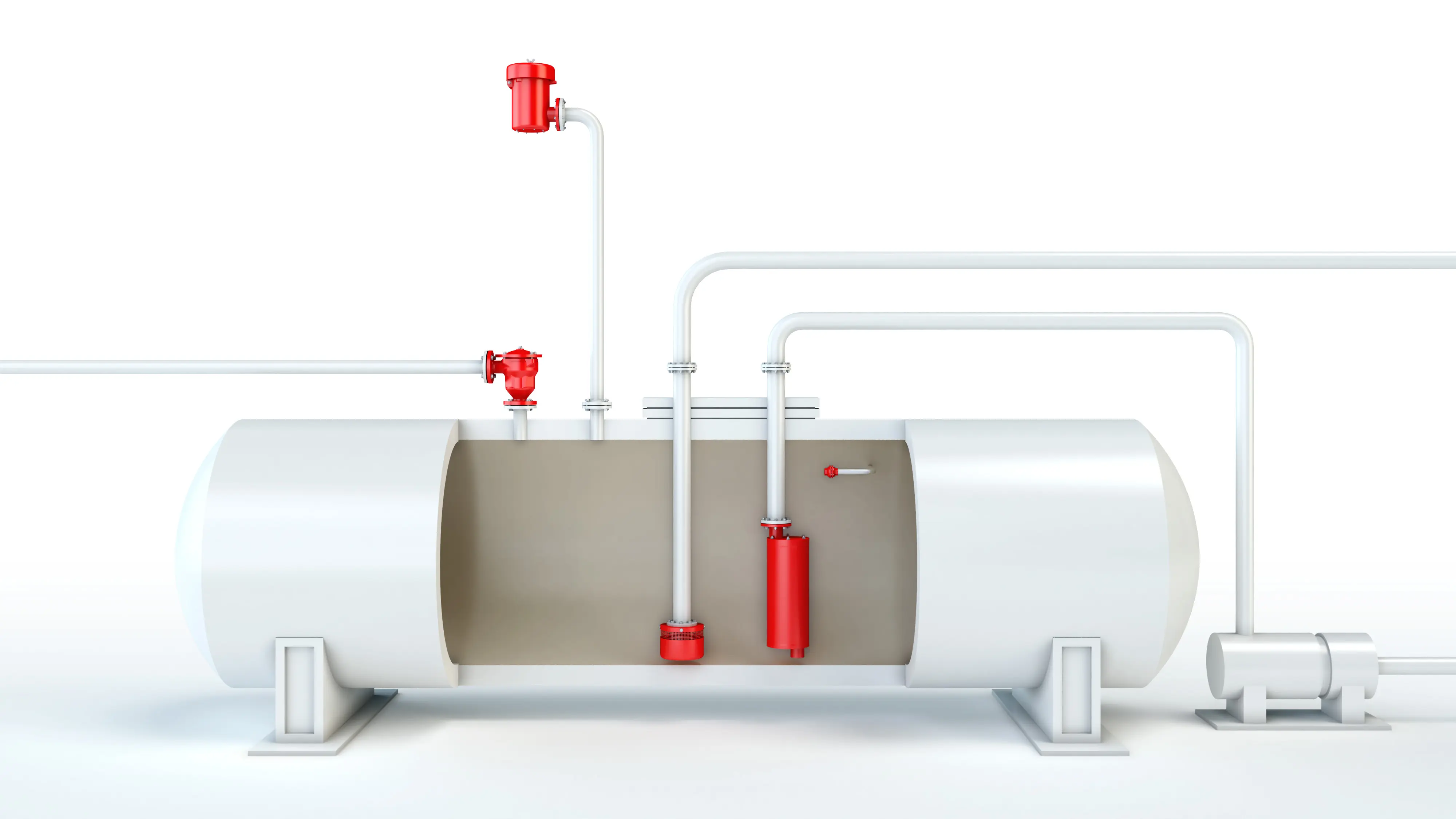
The PROTEGO® LDA Series of Liquid Detonation Arresters was developed for storage tank filling lines that are not continuously filled with product and sometimes contain a combustible mixture. The device Appareil A device is a pipe component that influences the media flow by opening, closing, or partially shutting off the flow channel or by dividing or mixing the media flow. is installed inside the tank at the end of the line and prevents the combustion from being transferred into the tank if the explosive atmosphere Atmosphère à risques d'explosion A mixture of air and flammable substance in the form of gases, vapors, mists or dusts under atmospheric conditions in which, after ignition, spreads to the entire unburned mixture. ignites. The liquid detonation arresters Arrête-flammes antidétonation Flame arrester designed to prevent the transmission of a detonation. function according to the siphon principle in which the liquid product serves as a liquid barrier to flame propagation.
Reduction of Flame Propagation Speed
When a highly accelerated pipe deflagration or detonation occurs, the combustion pressure and flame propagation speed is substantially reduced by the design, converted into a low-energy deflagration, and then stopped by the remaining immersion liquid.

For Explosion Groups IIA to IIB3
The application range for the device is a product vapor/air mixture temperature of up to + 60°C / 140°F and an absolute pressure up to 1.1 bar / 15.9 psi. This covers all possible operating conditions of empty lines for flammable liquids. The liquid detonation arrester is pressure-resistant up to 10 bar / 145 psi. The device protects against nearly all flammable liquids and is approved for explosion groups IIA to IIB3 (NEC group D to C MESG ≥ 0.65 mm). EU conformity according to the currently valid ATEX directive. Approvals according to other national/international regulations on request.
Dimensiones
To select the nominal size Diamètre nominal The nominal size is an alphanumeric designation of size for components in a piping system, used for reference purposes, comprising the letters DN followed by a dimensionless integer that is indirectly related to the physical size of the bore or outside diameter of the connections, expessed in millimeters. (DN), please use the flow capacity chart on the following pages
| DN | 25 / 1" | 32 / 1¼“ | 40 / 1½“ | 50 / 2" | 65 / 2½“ | 80 / 3" | 100 / 4" | 125 / 5" | 150 / 6" | 200 / 8" | 250 / 10" |
| a | 500 / 19.69 | 580 / 22.83 | 700 / 27.56 | 700 / 27.56 | 825 / 32.48 | 925 / 36.42 | 1050 / 41.34 | 1150 / 45.28 | 1350 / 53.15 | 1650 / 64.96 | 2000 / 78.74 |
| b | 538 / 21.18 | 620 / 24.41 | 745 / 29.33 | 745 / 29.33 | 870 / 34.25 | 975 / 38.39 | 1102 / 43.39 | 1205 / 47.44 | 1405 / 55.31 | 1712 / 67.40 | 2068 / 81.42 |
| c | 725 / 28.54 | 805 / 31.69 | 925 / 36.42 | 925 / 36.42 | 1050 / 41.34 | 1145 / 45.08 | 1270 / 50.00 | 1380 / 54.33 | 1580 / 62.20 | 1880 / 74.02 | 2300 / 90.55 |
| d | 115 / 4.53 | 140 / 5.51 | 168 / 6.61 | 168 / 6.61 | 220 / 8.66 | 245 / 9.65 | 325 / 12.80 | 356 / 14.02 | 500 / 19.69 | 600 / 23.62 | 700 / 27.56 |
| e | 50 / 1.97 | 58 / 2.28 | 65 / 2.56 | 65 / 2.56 | 95 / 3.74 | 105 / 4.13 | 135 / 5.31 | 155 / 6.10 | 200 / 7.87 | 250 / 9.84 | 300 / 11.81 |
Dimensiones en mm / pulgadas
Selección de materiales para la vivienda
| Design | A | B |
| Housing | Steel | Stainless Steel |
| Gasket | PTFE | PTFE |
Special materials upon request
Selección del grupo de explosión
| MESG | Expl. Gr. (IEC / CEN) | Gas Group (NEC) |
| > 0,90 mm | IIA | D |
| ≥ 0,65 mm | IIB3 | C |
Special approvals upon request
Especificación de la máx. temperatura de operación
| ≤ 60°C / 140°F | Tmaximum allowable operating temperature Operating temperature Temperature reached when the equipment is operating under design conditions. in °C |
| - | Designation |
higher operating temperatures upon request
Tipo de bridas de conexión
| EN 1092-1; Form B1 |
| ASME B16.5 CL 150 R.F. |
other types upon request
Outlet type
| Straight pipe | I |
| Beveled pipe | II |
| EN 1092-1, Form B1 or DIN 2501, Form C | III (EN or DIN) |
| ASME B16.5 CL 150 R.F. | III (ASME) |
other types upon request
Diagrama de flujo volumétrico
The volume flow V in m³/h was determined with water according to DIN EN 60534 at a temperature Tn = 20°C and an atmospheric pressure pn = 1,013 bar, kinematic viscosity v = 10-6 m²/s
To avoid electrostatic charge of flammable liquids the maximum flow is limited (refer to TRGS 727, CENELEC-Report CLC/TR 60079-32-1).