Características
Función y descripción
Highly Developed Pressure Relief Valve
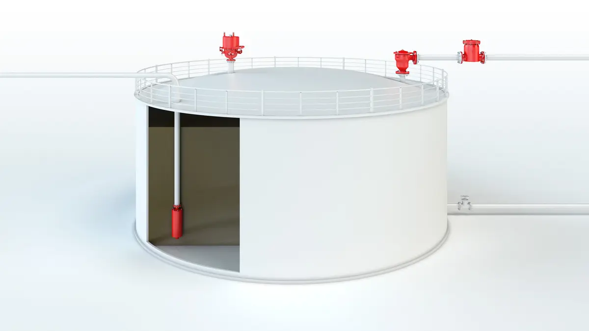
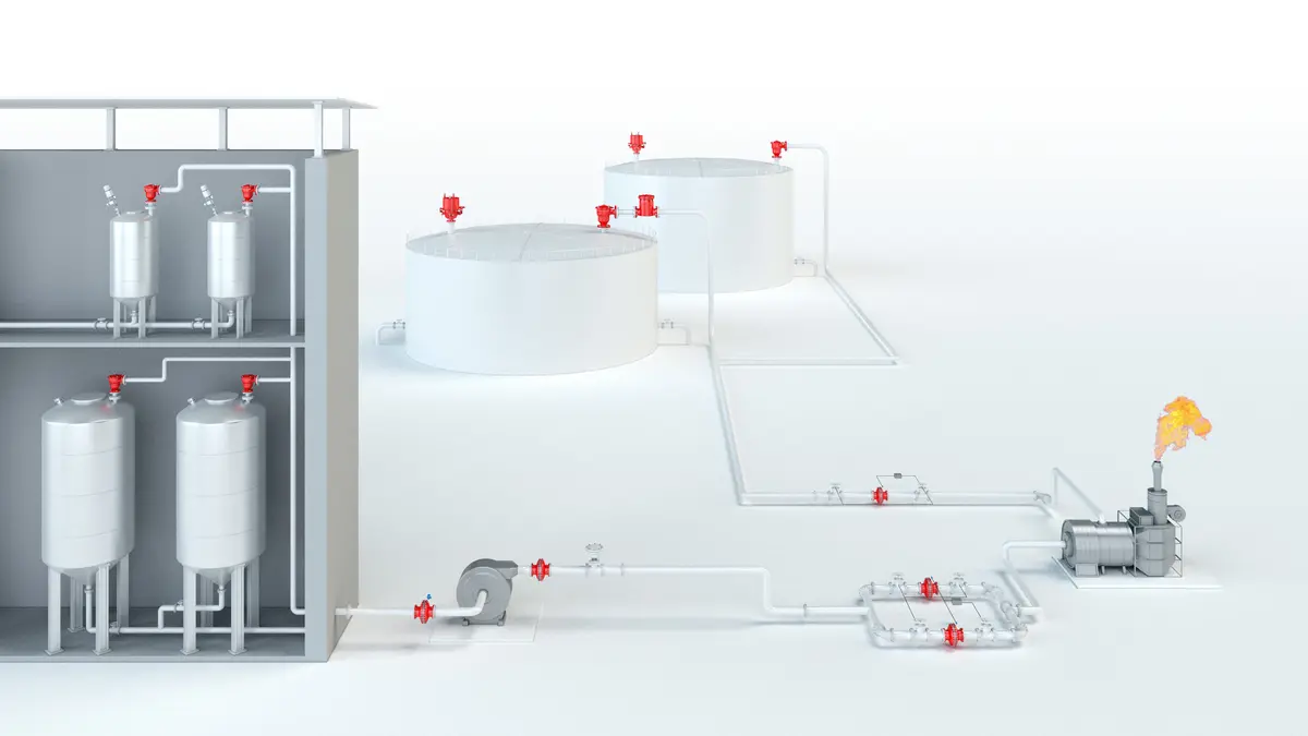
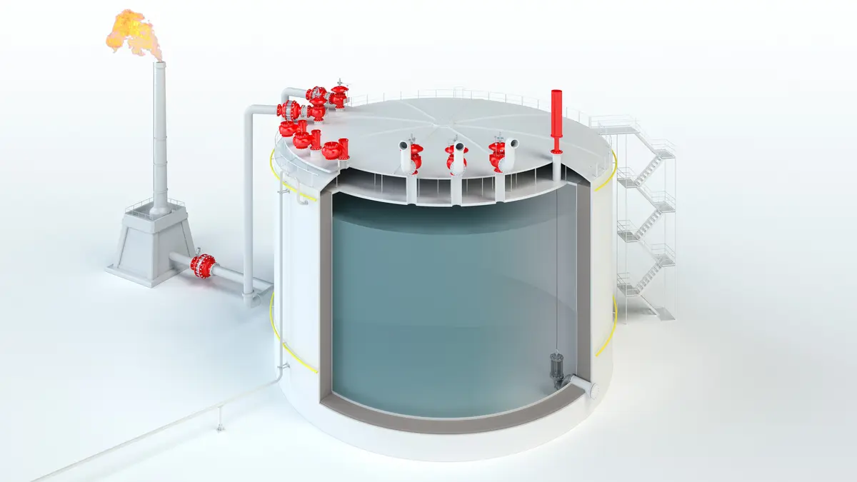
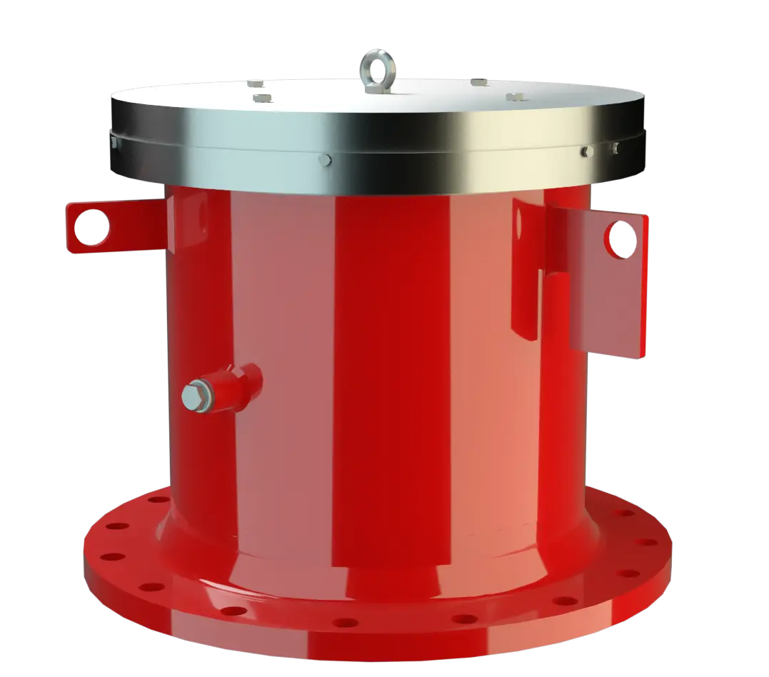
The ER/V Type PROTEGO® valve is a highly developed emergency pressure relief valve Soupape de surpression Valve designed to open and relieve excess pressure and to reclose and prevent the further flow of fluid after normal conditions have been restored. with high flow capacity. It is primarily used as a device Appareil A device is a pipe component that influences the media flow by opening, closing, or partially shutting off the flow channel or by dividing or mixing the media flow. for emergency pressure relief for storage tanks, containers, silos, and process engineering equipment; it offers reliable protection against overpressure Surpression Overpressure refers to an increase in pressure in a system or vessel above the normal operating pressure. and prevents impermissible product vapor loss close to the set pressure Pression de réponse Set pressure is the gauge pressure at the device inlet at which the relief device is set to start opening under service conditions. . It is designed to relief particularly large amounts to prevent the vessel Récipient Container or structural envelope in which materials are processed, treated or stored. from rupturing in an emergency case.
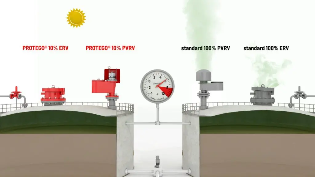
Full Lift Technology
The device will start to open as soon as the set pressure is reached and only requires 10% overpressure to full lift Course Lift is the actual travel of the valve pallet from the main valve out of the closed position. . Continuous investments into research and development have allowed PROTEGO® to develop a low pressure valve which has the same opening characteristic as a high pressure safety relief valve. This “Full Lift Type” technology allows the valve to be set just 10% below the maximum allowable working pressure of the tank and still safely vent the required mass flow.
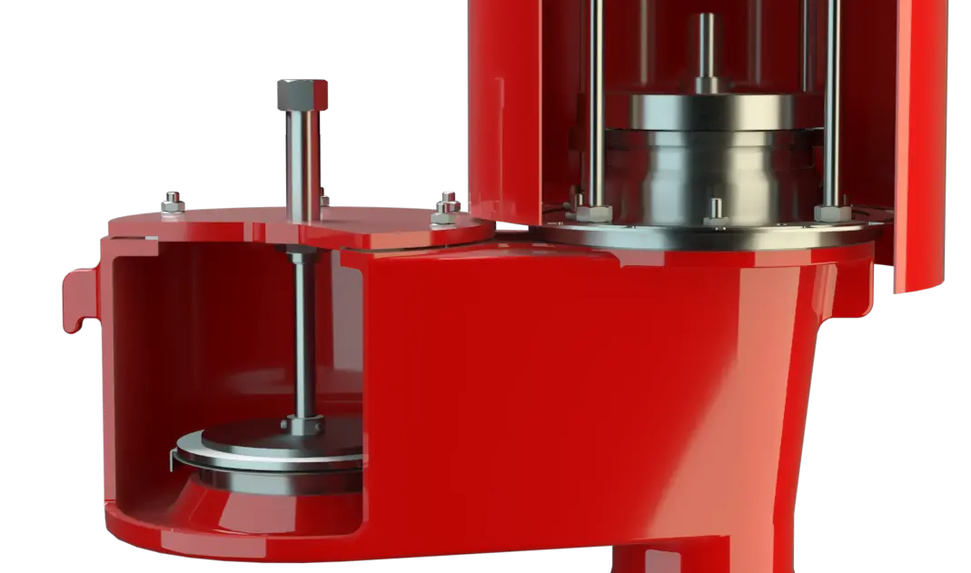
Advanced Manufacturing Technology
Due to the highly developed manufacturing technology, the tank pressure Pression de la cuve Tank pressure is the pressure within a tank. is maintained up to the set pressure, with a tightness that is far superior to the conventional standard. This feature is achieved by valve seats made of stainless steel with an inserted O-ring Joint torique O-rings are ring-shaped gaskets with a round, o-shaped cross section seal Joint A seal prevents or limits unwanted transfer of product from one container to another. Seal is used as superordinate term for all types of sealing elements. , a precisely lapped valve pallet Clapet Valve pallet is the generic term for the assembly that rests on the valve seat. , as well as a reinforced housing Corps A housing is a solid shell, which surrounds a content, either protecting the content from external influences, or protecting the environment from the content. design. After the excess pressure is relieved, the valve reseats and provides a tight seal again.
Dimensiones
To select the nominal size Diamètre nominal The nominal size is an alphanumeric designation of size for components in a piping system, used for reference purposes, comprising the letters DN followed by a dimensionless integer that is indirectly related to the physical size of the bore or outside diameter of the connections, expessed in millimeters. (DN), use the flow capacity chart on the following page
| DN | 200 / 8" | 250 / 10" | 300 / 12" | 350 / 14" | 400 / 16" | 450 / 18" | 500 / 20" | 600 / 24" | 700 / 28" |
| a | 305 / 12.01 | 375 / 14.76 | 425 / 16.73 | 445 / 17.52 | 495 / 19.49 | 545 / 21.46 | 615 / 24.21 | 715 / 28.15 | 795 / 31.30 |
| b | depending on pressure setting |
Dimensiones en mm / pulgadas
Selección de materiales
| Design | A | B | C | D |
| Housing | Steel | Steel | Stainless Steel | Stainless Steel |
| Valve seat | Stainless Steel | Stainless Steel | Stainless Steel | Stainless Steel |
| Valve pallet | Aluminium* | Steel-Stainless Steel* | Aluminium* | Stainless Steel* |
| Sealing | FPM | FPM | FPM | FPM |
* depending on pressure setting
Special materials upon request
Tipo de bridas de conexión
| EN 1092-1; Form B1 |
| ASME B16.5 CL 150 R.F. |
other types upon request
Modelo y especificación
The valve pallet is weight-loaded. Higher pressures are achieved with levers (see ER/VH) or with spring Ressort A spring is a spiral of wire which returns to its original shape after it is pressed or pulled. -loading (see ER/V-F).Additional special devices available upon request.
Settings
| DN 200 to DN 350 | +5 mbar | +40 mbar |
| +2 inch W.C.J | +16 inch W.C. | |
| DN 400 to DN 700 | +5 mbar | +25 mbar |
| +2 inch W.C.J | +10 inch W.C. |
For higher pressure settings, see types ER/VH and ER/V-F.
Diagrama de flujo volumétrico
Los diagramas de flujo volumétrico han sido determinados con un banco de pruebas de caudal calibrado y certifi - cado por TÜV. El flujo volumétrico V. en [m³/h] y el CFH se refi eren a las condiciones estándar de referencia de aire según ISO 6358 (20°C, 1bar). La conversión a otras densidades y temperaturas están referidas en el Vol. 1: “Fundamentos Técnicos”.