DR/SV
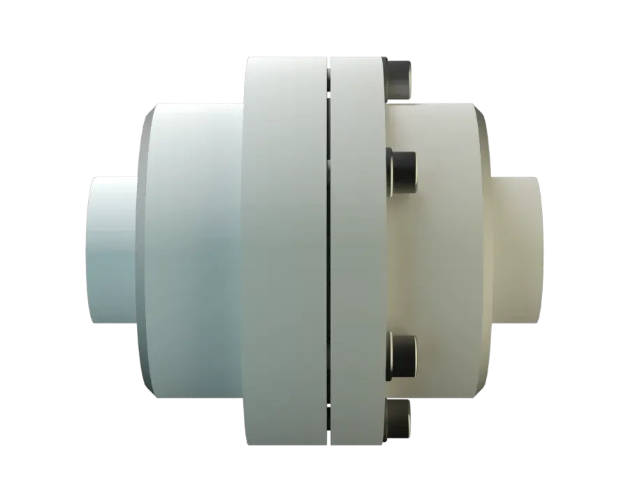
In-Line Detonation Flame Arrester with shut-off valve, for stable detonations and deflagrations in a straight through design, unidirectional
Características
Función y descripción
Detonation Arrester With the Advantages of a Shut-Off Valve
The PROTEGO® DR/SV Flame Arrester Series ideally combines the function of a detonation arrester Arrête-flammes antidétonation Flame arrester designed to prevent the transmission of a detonation. with the advantages of a Shut-Off Valve. In case of ignition, the fire can be stabilized within the Flame Arrester when the flammable gas continues to flow. Inside the detonation arrester, is a valve (1) that closes in case of fire, stops the additional supply of fuel and extinguishes the flames.
Suction-Side Protection for Compressors and Pumps
Temperature sensors in combination with an emergency switch off do not have to be installed if the type PROTEGO® DR/SV device Appareil A device is a pipe component that influences the media flow by opening, closing, or partially shutting off the flow channel or by dividing or mixing the media flow. is used. This device is particularly useful for the sucction-side protection of compressors and pumps.

For Explosion Group IIA
Once a detonation enters the Flame Arrester, energy is absorbed from the detonation shock wave by the central plate disc (2) before the flame is extinguished in the narrow gaps of the two FLAMEFILTER® discs (3). This device can be used for fluids of explosion group IIA (NEC group D). The In-Line Detonation Flame Arresters are unidirectional and equipped with a threaded connection. The thread can be executed to international standards. The standard design can be used up to an operating temperature Operating temperature Temperature reached when the equipment is operating under design conditions. of +60°C / 140°F and an (absolute) operating pressure Pression de service Operating pressure is the pressure existing at normal operating conditions within the system being protected. up to 1.1 bar / 15,9 psi. EU conformity according to the currently valid ATEX directive. Approvals according to other national/international regulations on request.
Dimensiones
To select the nominal size Diamètre nominal The nominal size is an alphanumeric designation of size for components in a piping system, used for reference purposes, comprising the letters DN followed by a dimensionless integer that is indirectly related to the physical size of the bore or outside diameter of the connections, expessed in millimeters. (DN), please use the flow capacity chart on the following page
| DN | G ½" | G ¾" |
| a | 115 / 4.53 | 115 / 4.53 |
| b | 100 / 3.94 | 100 / 3.94 |
Dimensiones en mm / pulgadas
Selección de materiales para la vivienda
| Design | A | B |
| Housing | Brass | Stainless Steel |
| Gasket | WS 3822 | WS 3822 |
| Flame arrester unit Flame arrester unit Flame arrester casing with FLAMEFILTER® set. | A | A, B |
Special materials upon request
Combinación de materiales para la unidad apagallamas
| Design | A | B |
| FLAMEFILTER®* | Stainless Steel | Stainless Steel |
| Spacer | Stainless Steel | Stainless Steel |
| Support for FLAMEFILTER® | Brass | Stainless Steel |
| Washer | Brass | Stainless Steel |
* the FLAMEFILTER® are also available in the materials Tantalum, Inconel, Copper, etc. when the listed housing Corps A housing is a solid shell, which surrounds a content, either protecting the content from external influences, or protecting the environment from the content. and cage materials are used.
Special materials upon request
Selección del grupo de explosión
| MESG | Expl. Gr. (IEC / CEN) | Gas Group (NEC) |
| > 0,90 mm | IIA | D |
Special approvals upon request
Selección de la máxima presión de operación
| DN | G ½" | G ¾" |
| Pmax | 1,1 / 15.9 | 1,1 / 15.9 |
Pmax = Maximum allowable operating pressure in bar / psi absolut, higher operating pressure upon request
Especificación de la máx. temperatura de operación
| ≤ 60°C / 140°F | Tmaximum allowable operating temperature in °C |
| - | Designation |
higher operating temperatures upon request
Tipo de conexión
| Pipe thread DIN ISO 228-1 | DIN |
other types of thread upon request
Diagrama de flujo volumétrico
Los diagramas de flujo volumétrico han sido determinados con un banco de pruebas de caudal calibrado y certifi - cado por TÜV. El flujo volumétrico V. en [m³/h] y el CFH se refi eren a las condiciones estándar de referencia de aire según ISO 6358 (20°C, 1bar). La conversión a otras densidades y temperaturas están referidas en el Vol. 1: “Fundamentos Técnicos”.