Características
Función y descripción
Protection Against Atmospheric Deflagrations
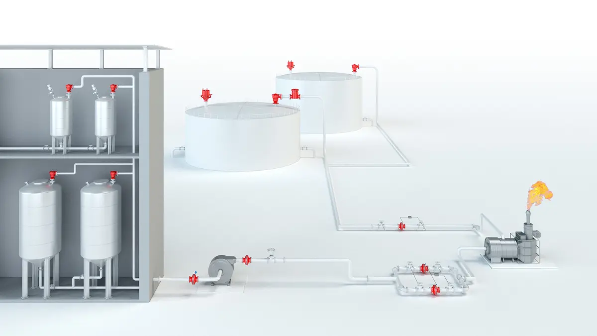
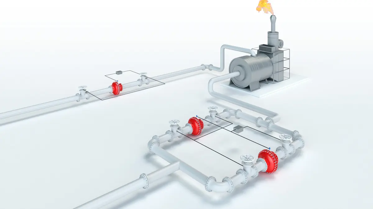
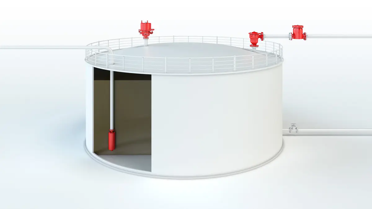
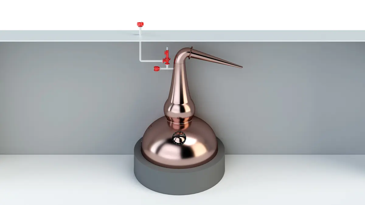
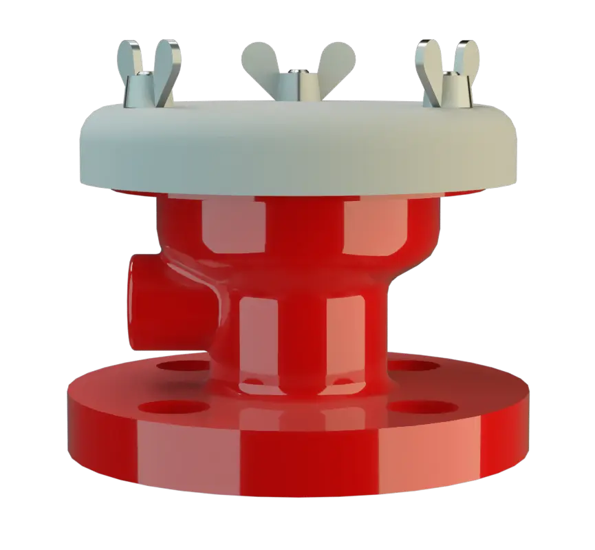
The PROTEGO® BE/AD End-of-Line Deflagration Flame Arrester Arrête-flammes antidéflagration Flame arrester designed to prevent the transmission of a deflagration. It can be an end-of-line flame arrester or an in-line flame arrester. provides protection against atmospheric deflagrations. The device Appareil A device is a pipe component that influences the media flow by opening, closing, or partially shutting off the flow channel or by dividing or mixing the media flow. is usually installed on vent lines of small vessels and plant equipment which are not pressurized. For safe application, it is important that an endurance burning Endurance burning Stabilized burning for an unlimited time. situation can be excluded. So typically, it is installed on vents lines which discharge vapor for a short time period. The device is the ideal solution for preventing flame transmission from atmospheric deflagration into the vessel Récipient Container or structural envelope in which materials are processed, treated or stored. or plant.
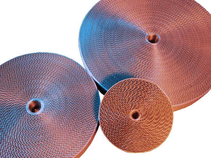
Main Component – PROTEGO® Flame Arrester Unit
The PROTEGO® BE/AD consists of the housing Corps A housing is a solid shell, which surrounds a content, either protecting the content from external influences, or protecting the environment from the content. (1), a weather hood Capot de protection contre les intempéries A weather hood is a cover to protect the internal components of a device from environmental influences. (2), and the PROTEGO® Flame Arrester Unit (3). The device is equipped with a metal weather hood. The FLAMEFILTER® gap size will depend on the device’s intended use.

For Explosion Groups IIA to IIC
Specifying the operating conditions, such as the temperature, pressure, explosion group, and the composition of the fluid, enables PROTEGO® to select the best End-of-Line Deflagration Flame Arrester for your application. The PROTEGO® BE/AD Series End-of-Line Deflagration Flame Arrester is available for substances from explosion groups IIA to IIC (NEC groups D to B). The standard design can be used with an operating temperature Operating temperature Temperature reached when the equipment is operating under design conditions. of up to +60°C / 140°F. EU conformity according to the currently valid ATEX directive. Approvals according to other national/international regulations on request.
Dimensiones
| DN | 15 / G ½" | 20 / G ¾" | 25 / G 1" | 32 / G 1¼" | 40 / G 1½" | 50 / G 2" |
| a | 116 / 4.57 | 116 / 4.57 | 116 / 4.57 | 116 / 4.57 | 200 / 7.87 | 200 / 7.87 |
| b | 80 / 3.15 | 80 / 3.15 | 85 / 3.35 | 85 / 3.35 | 150 / 5.91 | 150 / 5.91 |
Dimensiones en mm / pulgadas
Selección de materiales
| Design | B | C | |
| Housing | Steel | Stainless Steel | Hastelloy |
| Weather Hood | Stainless Steel | Stainless Steel | Stainless Steel |
| FLAMEFILTER® | Stainless Steel | Stainless Steel | Hastelloy |
Special materials upon request
Selección del grupo de explosión
| MESG | Expl. Gr. (IEC / CEN) | Gas Group (NEC) |
| ≥ 0,65 mm | IIB3 | C |
| < 0,5 mm | IIC | B |
Special approvals upon request
Especificación de la máx. temperatura de operación
| ≤ 60°C / 140°F | Tmaximum allowable operating temperature in °C |
| - | Designation |
higher operating temperatures upon request
Tipo de conexión
| Pipe thread DIN ISO 228-1 | DIN |
other types of thread upon request
Modelo y especificación
Following designs are available:Special designs available on request
Diagrama de flujo volumétrico
Los diagramas de flujo volumétrico han sido determinados con un banco de pruebas de caudal calibrado y certifi - cado por TÜV. El flujo volumétrico V. en [m³/h] y el CFH se refi eren a las condiciones estándar de referencia de aire según ISO 6358 (20°C, 1bar). La conversión a otras densidades y temperaturas están referidas en el Vol. 1: “Fundamentos Técnicos”.